Wearable Biosensors for Continuous Health Monitoring: Technologies, Applications, and Future Trends in Biomedical Research
This article provides a comprehensive analysis of wearable biosensors for continuous health monitoring, tailored for researchers, scientists, and drug development professionals.
Wearable Biosensors for Continuous Health Monitoring: Technologies, Applications, and Future Trends in Biomedical Research
Abstract
This article provides a comprehensive analysis of wearable biosensors for continuous health monitoring, tailored for researchers, scientists, and drug development professionals. It explores the foundational principles and evolution of biosensing technologies, from early electrocardiogram monitors to modern microneedle arrays and sweat-based platforms. The review delves into methodological advances in electrochemical, optical, and piezoelectric sensing modalities and their specific applications in therapeutic drug monitoring, chronic disease management, and vital sign tracking. The article critically examines persistent technological challenges, including selectivity, stability, and biofouling, while presenting validation frameworks and comparative performance analyses across sensing modalities. By synthesizing current research and market trends, this work aims to inform the development of next-generation biosensors and their integration into personalized medicine and decentralized clinical trials.
The Evolution and Core Principles of Wearable Biosensing Technology
The evolution from the bulky, intrusive biomonitoring systems of the Apollo era to today's seamless epidermal electronics represents a profound transformation in healthcare monitoring. This trajectory mirrors advancements in material science, microelectronics, and a deepening understanding of human physiology. The foundational work conducted by NASA during the Mercury, Gemini, and Apollo programs established the critical need for continuous physiological monitoring in extreme environments [1]. These early systems, while revolutionary for their time, posed significant challenges in terms of astronaut comfort and signal reliability. Today, the field of epidermal electronics is overcoming these historical limitations through devices characterized by exceptional softness, breathability, and mechanoelectrical stability, enabling high-fidelity, long-term health monitoring that seamlessly integrates with the human body [2]. This application note details the key technological milestones along this journey and provides structured experimental protocols for modern epidermal electronic systems, contextualized within ongoing research for continuous health monitoring.
Historical Progression & Quantitative Analysis
The biomedical monitoring systems developed for NASA's early spaceflight programs were driven by a fundamental need to understand the human body's response to the novel environment of space. Key concerns included cardiovascular function in weightlessness, fluid distribution, and physiological adaptations upon return to Earth [1]. The initial solutions, though functional, were characterized by a mechanical and intrusive approach.
Apollo-Era Biomonitoring Systems:
- Electrocardiogram (ECG): Monitored via electrodes with orange wires connected to signal conditioners designed to reject noise from movement and vibration [1].
- Respiration: Initially tracked via a heated thermistor placed in front of the mouth, which was later replaced by an impedance pneumograph technique that measured changes in chest tissue impedance during breathing [1].
- Temperature: Measured using a rectal probe for high accuracy, later replaced with an oral sensor for Gemini and Apollo missions due to astronaut discomfort [1].
- Blood Pressure: Assessed using a semiautomatic sphygmomanometer with a pressure cuff and microphone [1].
The transition to modern epidermal electronics has been enabled by a paradigm shift in design philosophy and material innovation, focusing on conformability, biocompatibility, and non-invasiveness.
Table 1: Quantitative Comparison of Biomonitoring Technologies Across Eras
| Monitoring Parameter | Apollo-Era Technology & Characteristics | Modern Epidermal Electronic Technology & Characteristics | Key Performance Advancements |
|---|---|---|---|
| Electrophysiological Signals (ECG, EMG, EEG) | Electrodes with wired connections to external signal conditioners; prone to motion artifacts [1]. | Soft, self-adhesive electrodes using materials like Au nanomesh or AgNW; serpentine structures for stretchability (up to 40-50%) [2] [3]. | High signal-to-noise ratio; seamless, long-term monitoring; resistance variation <1.2% after 50,000 bending cycles [2]. |
| Respiration | Impedance pneumography with electrodes placed near the 6th rib [1]. | Thin-film, breathable sensors capable of detecting chest wall movement via capacitive or impedance methods [2]. | Improved comfort for long-term use; high-fidelity data without skin irritation. |
| Temperature | Rectal probe (Mercury); Teflon-coated oral probe (Apollo) [1]. | Ultra-thin, skin-conformable thermistors based on piezoresistive/thermoresistive principles [2]. | Non-invasive, continuous monitoring; minimal discomfort. |
| Biochemical Sensing (e.g., Lactate, Glucose) | Largely unavailable during Apollo missions. | Electric Double Layer (EDL)-based biosensors and graphene-based electrochemical sensors analyzing sweat or interstitial fluid [4] [3]. | Real-time, non-invasive tracking of biomarkers; high sensitivity and selectivity enabled by nanomaterials [4]. |
| Mechanical Integrity | Rigid or flexible substrates with mechanical mismatch to skin. | Structures such as serpentine, kirigami, and 3D helical designs; use of liquid metals (e.g., Galinstan) [2] [3]. | Excellent stretchability (>30%), comfort, and mechanoelectrical stability for long-term use [2]. |
Table 2: Core Material Properties in Modern Epidermal Electronics
| Material Category | Example Materials | Key Properties | Typical Applications |
|---|---|---|---|
| Metallic Materials | Gold (Au), Silver Nanowires (AgNW), Galinstan [3] | High electrical conductivity (e.g., AgNW: 10^4–8×10^5 S/m), stretchability through structural design [2] [3]. | Conductors, electrodes, and sensing elements. |
| Polymeric Substrates | Polydimethylsiloxane (PDMS), Polyimide, Polyurethane (PU) [3] | High flexibility, biocompatibility, tunable mechanical strength (e.g., PDMS: 1-5 MPa) [3]. | Flexible substrate and encapsulation. |
| Conductive Polymers | PEDOT, Polypyrrole, Polyaniline [3] | Moderate conductivity (e.g., PEDOT: 300-1000 S/m), good mechanical properties [3]. | Electrodes, hole transport layers, biosensors. |
| Nanomaterials | Graphene, Carbon Nanotubes (CNTs) [4] | High surface area, excellent electrical and mechanical properties, biocompatibility [4]. | Enhancing sensitivity and selectivity in biosensors. |
| Biomaterials | Chitosan, Hyaluronic Acid, Collagen [3] | Biocompatibility, biodegradability, low conductivity (e.g., Chitosan: 10^-5–10^-4 S/m) [3]. | Bio-interfaces, hydrogels for sweat analysis. |
Experimental Protocols
Protocol: Fabrication of a Stretchable Nanomesh Epidermal Electrode
This protocol outlines the fabrication of highly soft, conformal-contact nanomesh electrodes for electrophysiological monitoring (e.g., ECG, EMG) [2].
1. Research Reagent Solutions & Essential Materials
Table 3: Essential Materials for Nanomesh Electrode Fabrication
| Item Name | Function/Explanation |
|---|---|
| Electrospinning Apparatus | A system including a high-voltage power supply, syringe pump, and grounded collector for producing polymer nanofibers. |
| Polymer Solution (e.g., Polyamide, PVA) | Serves as the sacrificial or structural template for the conductive nanomesh. |
| Silver Nanowire (AgNW) Dispersion | Forms the conductive network of the nanomesh. AgNWs provide high conductivity and mechanical flexibility. |
| Electrospray Attachment | Used to simultaneously deposit the AgNW dispersion onto the electrospun nanofibers. |
| Etching Solution (e.g., Water) | Selectively removes the sacrificial polymer fiber template if required, leaving a freestanding AgNW nanomesh. |
2. Step-by-Step Workflow:
- Solution Preparation: Prepare a homogeneous polymer solution (e.g., 10% w/v Polyamide in formic acid) and a well-dispersed AgNW suspension in a suitable solvent (e.g., ethanol).
- Simultaneous Electrospinning/Electrospraying: Mount the polymer syringe and the AgNW dispersion syringe on the apparatus. Simultaneously initiate electrospinning of the polymer and electrospraying of the AgNWs onto a rotating drum collector.
- Critical Parameters: Applied voltage (10-20 kV), flow rate (0.5-2 mL/h), tip-to-collector distance (10-20 cm), and ambient temperature/humidity [2].
- Transfer to Substrate: The resulting hybrid nanomesh mat, with AgNWs coated on the polymer fibers, can be directly transferred onto a temporary tattoo paper or a stretchable substrate like PDMS.
- Template Removal (Optional): If a pure metallic nanomesh is desired, immerse the structure in a solvent that dissolves the sacrificial polymer template (e.g., water for PVA), leaving a freestanding AgNW network.
- Characterization: Validate the electrical conductivity (e.g., sheet resistance ~4.14 Ω sq⁻¹) and mechanical properties (e.g., stretchability up to 50%) [2].
Diagram 1: Nanomesh electrode fabrication workflow.
Protocol: Functionalization of a Graphene-Based Sweat Biosensor
This protocol describes the modification of a graphene-based electrochemical sensor for continuous, non-invasive monitoring of biomarkers (e.g., glucose, lactate) in sweat [4] [5].
1. Research Reagent Solutions & Essential Materials
Table 4: Essential Materials for Graphene-Based Sweat Biosensor
| Item Name | Function/Explanation |
|---|---|
| Graphene Electrode | The transduction element; high surface area and excellent electrical conductivity form the sensor's foundation. |
| Specific Enzyme (e.g., Glucose Oxidase for Glucose Sensing) | The biorecognition element that selectively catalyzes a reaction with the target biomarker. |
| Cross-linking Agent (e.g., Glutaraldehyde) | Forms stable covalent bonds to immobilize the enzyme onto the graphene surface. |
| Nafion Solution | A permeslective membrane coating that reduces interference from other electroactive species in sweat (e.g., ascorbic acid, uric acid). |
| Chitosan | A biocompatible polymer often used as a matrix to entrap and stabilize enzymes on the electrode surface. |
2. Step-by-Step Workflow:
- Electrode Pretreatment: Clean the graphene working electrode sequentially with ethanol and deionized water, then perform electrochemical activation (e.g., via cyclic voltammetry in a suitable buffer) to introduce functional groups.
- Enzyme Immobilization: Prepare an immobilization cocktail containing the specific enzyme (e.g., 10 mg/mL Glucose Oxidase), a cross-linker (e.g., 2.5% glutaraldehyde), and a matrix polymer (e.g., 1% chitosan). Deposit a precise volume (e.g., 5 µL) onto the graphene electrode and allow it to cross-link at room temperature.
- Membrane Coating: To enhance selectivity, coat the modified electrode with a thin layer of Nafion (e.g., 1 µL of 0.5% solution) and allow it to dry.
- Calibration and Validation: Calibrate the sensor in artificial sweat or buffer solutions with known concentrations of the target analyte using amperometry (e.g., at +0.5V vs. Ag/AgCl). Correlate the measured current output with analyte concentration.
Diagram 2: Biosensor functionalization and calibration process.
The Scientist's Toolkit
Table 5: Key Research Reagent Solutions for Epidermal Electronics
| Item Name | Function/Explanation | Representative Use Case |
|---|---|---|
| Silver Nanowires (AgNWs) | Provide a conductive, transparent, and flexible network for electrodes and interconnects [2] [3]. | Fabrication of stretchable nanomesh electrodes for ECG monitoring [2]. |
| Liquid Metal (Galinstan) | Offers exceptional stretchability and self-healing properties for circuits on soft substrates [3]. | Creating ultra-stretchable wires and sensors that can withstand extreme deformation. |
| Conductive Polymer (PEDOT:PSS) | A biocompatible, flexible polymer with mixed ionic-electronic conductivity, ideal for interfacing with biological tissues [3]. | Used as a coating for electrodes to improve signal quality in electrophysiology. |
| Graphene Inks | Enable printing of high-performance, flexible sensing components with excellent electrical properties [4]. | Screen-printing electrodes for electrochemical detection of biomarkers in sweat. |
| Polydimethylsiloxane (PDMS) | A silicone elastomer used as a soft, flexible, and transparent encapsulant or substrate [3]. | Encapsulating fragile electronic components to create a robust, skin-worn patch. |
| Electrospinning Polymer (PVA, Polyamide) | Used to create fibrous templates (sacrificial or structural) for forming breathable, porous electronic membranes [2]. | Forming the scaffold for a breathable nanomesh electrode. |
| Chitosan | A biocompatible and biodegradable polysaccharide used as a hydrogel matrix for enzyme immobilization [3] [5]. | Entrapping glucose oxidase on the surface of a sweat sensor to enhance stability. |
| Nafion Solution | A permeslective membrane that minimizes fouling and interference from undesired anions in complex biofluids [5]. | Coating a lactate biosensor to improve selectivity in sweat analysis. |
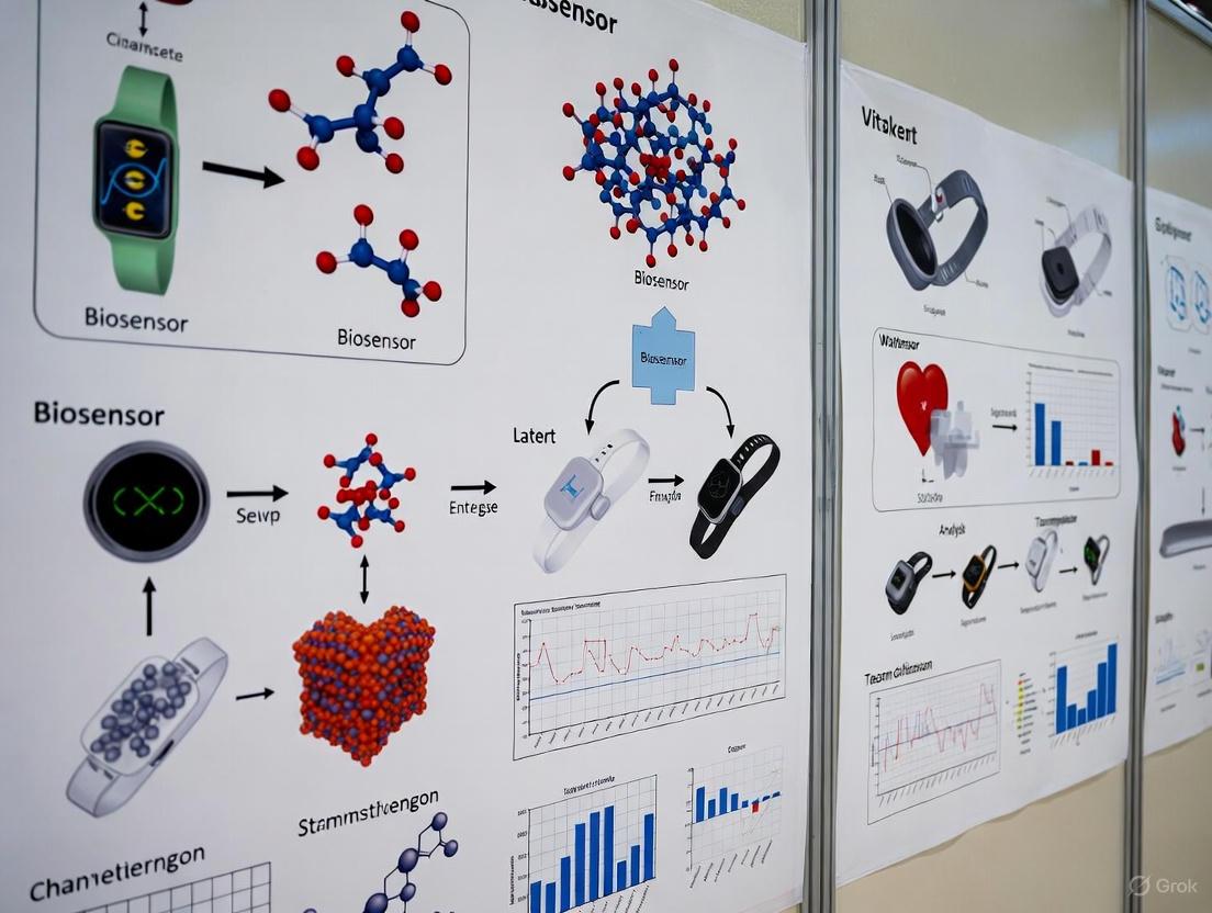
Biosensors are powerful analytical devices that combine a biological recognition element with a transducer to detect specific analytes, enabling rapid and sensitive diagnostics. Originally pioneered over 55 years ago with the development of the glucose oxidase electrode, biosensor technology has since expanded dramatically, finding critical applications in healthcare, environmental monitoring, and food safety [6]. In the context of wearable technologies for continuous health monitoring, understanding the fundamental architecture of biosensors is paramount for developing devices capable of non-invasive, real-time tracking of physiological biomarkers [7] [4]. This document outlines the core components, operational principles, and practical methodologies central to biosensor design and implementation, with particular emphasis on applications in continuous health monitoring research.
Core Components of a Biosensor
All biosensors consist of three fundamental components that work in concert to detect and quantify a target analyte: a biorecognition element for specific sequestration, a transducer for converting the biological event into a measurable signal, and a signal processor for interpreting the output [6] [8]. The synergistic operation of these components enables the translation of a biochemical binding event into quantifiable analytical data.
Biorecognition Elements
The biorecognition element provides the specificity critical for targeted analyte detection. These elements can be biologically derived or synthetically engineered, each with distinct characteristics influencing overall biosensor performance in terms of sensitivity, selectivity, reproducibility, and reusability [6].
Table 1: Comparison of Common Biorecognition Elements
| Biorecognition Element | Type | Binding Mechanism | Key Advantages | Key Limitations |
|---|---|---|---|---|
| Antibody [6] | Natural (Affinity-based) | Forms a 3D immunocomplex with antigen | High specificity and accuracy | Costly production; limited stability |
| Enzyme [6] | Natural (Catalytic) | Catalytic conversion of analyte | High sensitivity; amplifies signal | Stability dependent on environment |
| Aptamer [6] | Pseudo-natural (Affinity-based) | Folding into 3D structure for target binding | High stability; tunable for various targets | SELEX discovery process is costly |
| Nucleic Acid (DNA) [6] | Natural (Affinity-based) | Complementary base-pairing | High predictability and specificity | Limited to nucleic acid targets |
| Molecularly Imprinted Polymer (MIP) [6] | Synthetic (Affinity-based) | Size, shape, and functional group complementarity | High stability and low cost | Can suffer from heterogeneity |
Transducers
The transducer is the component that converts the biological recognition event into a quantifiable electrical or optical signal. The choice of transducer defines the primary classification of the biosensor and is crucial for determining sensitivity and applicability [8].
- Electrochemical Transducers: These are among the most common, particularly in point-of-care and wearable devices. They measure electrical changes—such as current (amperometric), potential (potentiometric), or impedance (impedimetric)—resulting from the biorecognition event. They are prized for their high sensitivity, low cost, and ease of miniaturization [8]. For example, the catalytic action of an enzyme like glucose oxidase generates a measurable current proportional to glucose concentration [6].
- Optical Transducers: These transducers detect changes in light properties, including absorbance, fluorescence, or refractive index (as in surface plasmon resonance). They offer high accuracy and are resistant to electromagnetic interference, making them suitable for complex biological matrices [8].
- Piezoelectric Transducers: These devices measure changes in mass or mechanical resonance upon binding of the target analyte. They are valuable as reliable diagnostic tools but can be less suited for miniaturized, wearable form factors [8].
Signal Processing
The signal processor, or reader device, acquires the raw signal from the transducer and converts it into user-interpretable data. This involves signal amplification, filtering, and quantification [8]. Advanced signal processing often employs techniques like differential pulse voltammetry (DPV) or electrochemical impedance spectroscopy (EIS) for electrochemical sensors [8]. The limit of detection (LOD) is a key metric calculated as LOD = 3σ/S, where σ is the standard deviation of the blank signal and S is the sensitivity of the sensor [8]. Integration with machine learning (ML) algorithms is an emerging trend that enhances data analysis, enables anomaly detection, and improves sensor performance by filtering out interference [8].
Biosensor Architecture and Workflow
The following diagram illustrates the integrated workflow and logical relationships between the core components of a typical biosensor system.
Application in Wearable Biosensors
The fundamental biosensor architecture is the foundation for the development of advanced wearable devices for continuous, non-invasive health monitoring. These devices leverage breakthroughs in material science and microfluidics to interface with the human body.
- Sampling Bodily Fluids: Wearable biosensors often analyze easily accessible biofluids like sweat, tears, or saliva, which contain a rich profile of physiological biomarkers [7] [9]. For instance, sweat-based wearable biosensors represent a new era for tracking metabolites and electrolytes [7], while tear-based sensors can monitor intraocular pressure and glucose levels [9].
- Integration of Nanomaterials: The use of nanomaterials, particularly graphene, has dramatically enhanced wearable biosensor performance. Graphene provides exemplary electrical properties, mechanical flexibility, and a tunable surface chemistry that allows for the effective immobilization of various biorecognition elements [4]. This is critical for creating durable, sensitive, and flexible sensing platforms.
- System Architecture: A typical wearable device integrates a flexible substrate holding the biosensor, which is often coupled with microfluidic channels for controlled fluid management (e.g., sweat sampling). The system includes the necessary electronics for signal transduction and processing, and increasingly features wireless connectivity for real-time data transmission to a smartphone or cloud-based platform [4].
Experimental Protocols
This section provides a detailed methodology for fabricating and characterizing a model electrochemical biosensor, a common platform for wearable health monitoring applications.
Protocol: Fabrication of a Graphene-Based Electrochemical Biosensor
Objective: To immobilize a biorecognition element (e.g., an enzyme or aptamer) on a graphene-based transducer and characterize its electrochemical performance [4] [8].
Materials:
- Graphene-modified screen-printed electrode (or a flexible graphene electrode)
- Biorecognition element solution (e.g., 1 mg/mL glucose oxidase in phosphate buffer)
- Coupling agents: EDC (1-Ethyl-3-(3-dimethylaminopropyl) carbodiimide) and NHS (N-Hydroxy succinimide)
- Phosphate Buffer Saline (PBS, 0.1 M, pH 7.4)
- Washing buffer (e.g., PBS with 0.05% Tween 20)
- Electrochemical probe solution (e.g., 5 mM [Fe(CN)₆]³⁻/⁴⁻ in PBS)
- Potentiostat
Procedure:
Electrode Pretreatment:
- Clean the graphene working electrode by performing 10 cycles of Cyclic Voltammetry (CV) in 0.1 M PBS (pH 7.4) from -0.2 V to +0.6 V (vs. Ag/AgCl reference) at a scan rate of 50 mV/s.
- Rinse the electrode thoroughly with deionized water and dry under a gentle stream of nitrogen gas.
Surface Functionalization:
- Prepare a fresh solution of 2 mM EDC and 5 mM NHS in deionized water.
- Deposit 10 µL of the EDC/NHS mixture onto the active surface of the graphene working electrode.
- Incubate for 1 hour at room temperature in a humid chamber to prevent evaporation.
- Rise the electrode gently with PBS to remove unreacted EDC/NHS.
Biorecognition Element Immobilization:
- Apply 10 µL of the biorecognition element solution (e.g., glucose oxidase) to the activated electrode surface.
- Incubate for 2 hours at 4°C in a humid chamber.
- After incubation, rinse the electrode with washing buffer to remove physically adsorbed molecules.
Blocking:
- To minimize non-specific binding, treat the electrode with 10 µL of 1% Bovine Serum Albumin (BSA) solution for 30 minutes.
- Rinse again with PBS and store in PBS at 4°C until use.
Protocol: Performance Characterization via Electrochemical Measurements
Objective: To evaluate the sensitivity, selectivity, and limit of detection (LOD) of the fabricated biosensor.
Procedure:
Electrochemical Characterization:
- Immerse the fabricated biosensor in a stirred electrochemical probe solution ([Fe(CN)₆]³⁻/⁴⁻).
- Record the CV from -0.2 V to +0.6 V at a scan rate of 50 mV/s. A successful immobilization is indicated by a decrease in the Faradaic current due to the insulating layer of biomolecules on the electrode surface.
- Perform Electrochemical Impedance Spectroscopy (EIS) in the same solution, applying a frequency range from 0.1 Hz to 100 kHz at a formal potential. Use the resulting Nyquist plot to quantify the electron transfer resistance (Rₑₜ).
Calibration and LOD Calculation:
- Prepare a series of standard solutions with known concentrations of the target analyte.
- Measure the amperometric response (e.g., at a constant potential of +0.5 V) of the biosensor upon successive additions of the standard solutions.
- Plot the steady-state current response against the analyte concentration to generate a calibration curve.
- Calculate the sensitivity (S) from the slope of the linear region of the calibration curve.
- The LOD is calculated using the formula: LOD = 3σ/S, where σ is the standard deviation of the blank signal (response in the absence of analyte) measured across multiple sensors (n≥3) [8].
The following diagram illustrates the specific mechanism of an enzymatic electrochemical biosensor, a foundational concept for many continuous monitoring devices.
The Scientist's Toolkit: Research Reagent Solutions
Table 2: Essential Materials for Biosensor Development
| Item / Reagent | Function / Application | Examples & Notes |
|---|---|---|
| Graphene Nanostructures [4] | Transducer material providing high electrical conductivity, flexibility, and large surface area for biomolecule immobilization. | Synthesized via chemical vapor deposition or from graphene oxide; ideal for wearable form factors. |
| Gold Nanoparticles (AuNPs) [8] | Nanomaterial for electrode modification; increases active surface area, enhancing signal and sensitivity. | Used in 3D nano/microislands (NMIs); compatible with thiol-based chemistry for biomolecule attachment. |
| EDC & NHS Crosslinkers [8] | Activate carboxyl groups on sensor surfaces to form stable amide bonds with amine-containing biomolecules (e.g., antibodies, aptamers). | Standard protocol for covalent immobilization; critical for stable and oriented surface attachment. |
| Thiol-Modified Aptamers [8] | Biorecognition elements immobilized on gold surfaces via strong Au-S bonds. | Provide high stability and selectivity; can be engineered via SELEX for various targets. |
| Molecularly Imprinted Polymers (MIPs) [6] | Synthetic biorecognition elements with templated cavities for target analyte. | Offer an alternative to biological receptors with superior stability and lower cost. |
| Polypyrrole Films [8] | Conducting polymer formed via electropolymerization; used to entrap enzymes and other biomolecules on electrode surfaces. | Provides a versatile and controllable matrix for biomolecule immobilization. |
The advancement of wearable biosensors is revolutionizing continuous health monitoring by providing real-time, non-invasive physiological data [10] [5]. For researchers and drug development professionals, the translation of a biosensing concept into a reliable diagnostic tool hinges on the rigorous characterization of its core analytical performance metrics [8]. These metrics—sensitivity, selectivity, limit of detection (LOD), and dynamic range—serve as the fundamental benchmarks that validate a sensor's capability to accurately and reliably quantify biomarkers in complex biological fluids like sweat, saliva, and interstitial fluid [11] [12].
Establishing these parameters is crucial for ensuring that data generated for clinical diagnostics, chronic disease management, such as diabetes, and fitness tracking meets the stringent requirements for regulatory approval and clinical acceptance [13] [11]. This document provides detailed application notes and experimental protocols for the precise determination of these critical metrics within the context of wearable biosensor development.
Core Metric Definitions and Quantitative Benchmarks
The table below defines the four core analytical metrics and presents quantitative examples from recent literature to illustrate their application in evaluating wearable biosensor performance.
Table 1: Core Analytical Performance Metrics and Representative Data from Wearable Biosensor Research
| Metric | Definition | Significance in Wearable Biosensors | Exemplary Performance from Recent Research |
|---|---|---|---|
| Sensitivity | The magnitude of signal change per unit change in analyte concentration [14]. | High sensitivity enables detection of low-abundance biomarkers crucial for early disease diagnosis [15]. | A glucose sensor achieved a sensitivity of 95.12 ± 2.54 µA mM⁻¹ cm⁻² [14]. |
| Selectivity | The sensor's ability to respond exclusively to the target analyte in the presence of interferents [8]. | Critical for accurate operation in complex biofluids (e.g., sweat, saliva) containing multiple chemical species [11]. | Specificity is conferred by the biorecognition element (e.g., enzyme, antibody, aptamer) [11] [8]. |
| Limit of Detection (LOD) | The lowest analyte concentration that can be reliably distinguished from a blank sample [8]. | Determines the utility for detecting biomarkers at their physiologically relevant low concentrations [15]. | A SERS-based miRNA sensor reported an LOD of 3.46 aM [15]. Calculated as LOD = 3σ/S, where σ is the standard deviation of the blank and S is sensitivity [8]. |
| Dynamic Range | The span of analyte concentrations over which the sensor provides a quantifiable response [14]. | Must encompass the physiologically relevant concentration range of the target biomarker for clinical utility [12]. | A fluorescent biosensor for a miRNA biomarker exhibited a dynamic range of 0.1–10 pM [15]. |
Experimental Protocols for Metric Validation
Protocol for Calibration Curve, Sensitivity, and LOD Determination
This protocol outlines the procedure for establishing a sensor's calibration curve, from which its sensitivity and Limit of Detection are derived.
1. Principle: A biosensor's response (e.g., current, voltage, fluorescence intensity) is measured across a series of standard solutions with known analyte concentrations. A calibration curve is constructed by plotting the signal against concentration, and its parameters are used to calculate sensitivity and LOD [14] [8].
2. Research Reagent Solutions: Table 2: Essential Reagents for Sensor Calibration and Validation
| Reagent/Material | Function/Explanation |
|---|---|
| Target Analyte Standard | High-purity reference material for preparing calibration solutions with known concentrations. |
| Buffer Solution (e.g., PBS) | Provides a stable ionic strength and pH background that mimics the intended biofluid. |
| Electrochemical Cell / Optical Cuvette | The container for the sample and sensor during measurement, ensuring consistent geometry. |
| Potentiostat / Spectrometer | Instrumentation to apply the excitation (electrical potential, light) and measure the resulting signal. |
3. Procedure:
- Preparation of Standard Solutions: Prepare a dilution series of the target analyte in an appropriate buffer (e.g., PBS, synthetic sweat). The concentration range should be designed to bracket the expected physiological and pathological levels.
- Sensor Measurement: For each standard solution, introduce the sensor and record the steady-state output signal. For electrochemical sensors, techniques such as Cyclic Voltammetry (CV) or Amperometry are commonly used [8]. For optical sensors, measure fluorescence intensity or absorbance.
- Data Analysis:
- Calibration Curve: Plot the measured signal (y-axis) against the analyte concentration (x-axis). Perform linear regression to obtain the equation of the best-fit line (y = mx + c), where
mis the slope. - Sensitivity Calculation: The slope of the calibration curve (
m) is the analytical sensitivity of the sensor [14]. - LOD Calculation: Measure the standard deviation (σ) of the signal from at least ten blank (analyte-free) solutions. Calculate the LOD using the formula: LOD = 3σ / m, where
mis the sensitivity from the calibration curve [8].
- Calibration Curve: Plot the measured signal (y-axis) against the analyte concentration (x-axis). Perform linear regression to obtain the equation of the best-fit line (y = mx + c), where
Protocol for Selectivity and Specificity Assessment
This protocol validates that the sensor's signal is generated primarily by the target analyte, even in the presence of structurally similar compounds or common biofluid constituents.
1. Principle: The sensor's response to the target analyte is compared to its response to potential interfering substances at physiologically relevant concentrations. A highly selective sensor will show a significantly stronger response to the target [8].
2. Research Reagent Solutions:
- Potential Interferents: Substances commonly found in the target biofluid (e.g., glucose for lactate sensors, ascorbic acid, uric acid, urea, common salts).
- Biorecognition Element: The key to selectivity (e.g., glucose oxidase, specific antibody, DNA aptamer) [11] [8].
3. Procedure:
- Identify Interferents: Compile a list of potential interfering species based on the composition of the target biofluid (e.g., sweat, ISF) and the sensor's operating principle.
- Prepare Solutions: Prepare separate solutions containing the target analyte at a fixed concentration (e.g., at the middle of its dynamic range) and solutions containing each potential interferent at a concentration at or above its maximum expected physiological level.
- Measure Response: Measure the sensor's signal for the target analyte solution and for each interferent solution.
- Calculate Selectivity Coefficient: The relative response is calculated as (SignalInterferent / SignalTarget) × 100%. A low percentage indicates high selectivity. A more formal parameter is the Selectivity Coefficient (k), where a value << 1 indicates high selectivity for the target over the interferent.
The Scientist's Toolkit: Key Research Reagent Solutions
The reliability of a wearable biosensor is fundamentally linked to the quality and properties of the materials and reagents used in its construction and operation. The following table details essential components.
Table 3: Essential Research Reagents and Materials for Wearable Biosensor Development
| Category / Item | Function / Rationale |
|---|---|
| Biorecognition Elements | |
| Enzymes (e.g., Glucose Oxidase) | Catalyze a specific reaction with the target analyte, producing a measurable product (e.g., H₂O₂) [8]. |
| Antibodies & Aptamers | Provide high-affinity binding for specific bioaffinity sensing (immunosensors, aptasensors), crucial for detecting proteins, hormones, or pathogens [8] [15]. |
| Nanomaterials | |
| Gold Nanoparticles (AuNPs) & Graphene | Enhance electrochemical signal transduction and provide a high-surface-area platform for immobilizing biorecognition elements, directly improving sensitivity [8] [5]. |
| Carbon Nanotubes (CNTs) | Promote electron transfer in electrochemical sensors and can be used as transducing materials [15]. |
| Sensor Platform & Fabrication | |
| Flexible Polymers (e.g., PDMS) | Provide stretchable, skin-conformable substrates that are essential for wearable comfort and robust signal acquisition during movement [10] [5]. |
| Conductive Inks (e.g., Ag/CNT) | Enable printing of lightweight, flexible electrodes and circuits on various substrates, facilitating mass production [5]. |
| Hydrogels | Act as a biocompatible interface for sweat sampling and transport, mediating between the skin and the sensor [5]. |
| Data Acquisition & Validation | |
| Potentiostat/Galvanostat | Core instrument for applying potential and measuring current in electrochemical biosensors [8]. |
| Synthetic Biofluid (e.g., Artificial Sweat) | Provides a consistent and standardized medium for initial sensor characterization and validation [12]. |
The advancement of wearable biosensors for continuous health monitoring has intensified the focus on biofluids that can be sampled minimally or non-invasively. While blood remains the clinical gold standard for biomarker analysis, its collection is invasive and intermittent. Consequently, research has shifted towards alternative biofluids—sweat, interstitial fluid (ISF), and tears—which offer complementary advantages for decentralized, real-time monitoring. This Application Note provides a comparative analysis of these key biofluids, detailing their composition, biomarker relevance, and associated sampling protocols to inform the development of next-generation wearable biosensing platforms.
Comparative Biofluid Analysis
The selection of an appropriate biofluid is contingent upon the target biomarker's concentration, correlation with systemic levels, and the feasibility of sampling. The table below summarizes the characteristic concentrations of key biomarkers across these biofluids, informing sensor design and development.
Table 1: Characteristic Biomarker Concentrations in Key Biofluids
| Biomarker | Blood | Interstitial Fluid (ISF) | Sweat | Tears | Key Clinical Relevance |
|---|---|---|---|---|---|
| Sodium (Na⁺) | 136-146 mM [16] | ~135.7 mM [16] | 10-100 mM [17] | ~142 mM [17] | Electrolyte balance, hydration status [17] |
| Potassium (K⁺) | 3.5-5.0 mM [16] | ~4.0 mM [16] | 1-10 mM [17] | ~25 mM [17] | Electrolyte balance, renal function [17] |
| Glucose | 4.4-6.6 mM (fasting) | Highly correlated with blood [16] | 0.01-0.2 mM [17] | Correlated with blood [17] | Diabetes management [16] [17] |
| Lactate | 0.5-2.2 mM (venous) | Highly correlated with blood [16] | 5-25 mM (exercise) [17] | Information Missing | Metabolic stress, exercise physiology [16] |
| Cortisol | 80-500 nM (total) [16] | 5-50 nM [16] | Detectable [17] | Detectable [17] | Stress response, endocrine disorders [17] |
| Proteins (e.g., Albumin) | ~40 g/L (Albumin) | ~52% lower than blood [18] | >1000x lower than blood/ISF [16] | Rich in proteins (e.g., lysozyme) [17] | Inflammation, systemic disease [18] |
Table 2: Comparative Advantages and Challenges for Biosensing
| Biofluid | Key Advantages | Primary Challenges & Considerations |
|---|---|---|
| Blood | Gold standard; richest biomarker profile; strong clinical validation. | Invasive collection; requires expertise; clotting risk; not ideal for continuous wearables [17]. |
| Interstitial Fluid (ISF) | High correlation with blood for many biomarkers; no clotting; minimal dilution [18] [16]. | Requires minimally invasive sampling (e.g., microneedles); concentration gradients for large molecules [18] [16]. |
| Sweat | Easy, non-invasive access; relatively large volumes; diverse biomarkers [19] [17]. | Variable composition; dilution and contamination; correlation with blood can be complex [19] [17]. |
| Tears | Non-invasive; direct correlation for some biomarkers (e.g., glucose) [17]. | Very low volumes; low analyte concentrations; sensor stability in ocular environment [17]. |
Experimental Protocols for Biofluid Sampling and Analysis
Protocol: Microneedle-Based Sampling of Interstitial Fluid (ISF)
Principle: Hollow or solid microneedles breach the stratum corneum to access ISF in the dermis, enabling extraction or in-situ sensing with minimal pain [18] [16].
Materials:
- Microneedle Array: Solid, hollow, or hydrogel-forming microneedles.
- ISF Collection/Sensing Patch: Integrates microfluidic channels and electrodes.
- Functionalization Reagents: Enzymes (e.g., glucose oxidase) or Molecularly Imprinted Polymers (MIPs) [20] [17].
- Adhesive Layer: Medical-grade adhesive for skin attachment.
- Readout System: Potentiostat or optical reader.
Procedure:
- Skin Site Preparation: Cleanse the application site (e.g., forearm, abdomen) with 70% ethanol and allow to dry.
- Microneedle Array Application: Apply the array using a custom applicator to ensure consistent penetration into the dermis.
- ISF Extraction/Sensing:
- Signal Transduction: Monitor electrochemical (amperometric/potentiometric) or optical signals continuously.
- Data Acquisition: Transmit data wirelessly (e.g., via Bluetooth) to a mobile device or cloud platform for real-time tracking [5].
Protocol: Continuous Monitoring in Sweat using a Microfluidic Patch
Principle: Eccrine sweat is collected autonomously via capillary microfluidics and analyzed in real-time using integrated electrochemical sensors [19] [17].
Materials:
- Microfluidic Patch: Hydrophilic polymer layer for capillary-driven flow.
- Electrochemical Sensors: Working, reference, and counter electrodes, often made from flexible carbon or graphene inks [5].
- Sweat Induction Module: Iontophoresis electrode (optional, for stimulation at rest).
- Hydrogel Interface: Ensures conformal contact with skin.
- Signal Processing Electronics: Miniaturized potentiostat and transmitter.
Procedure:
- Sensor Patch Integration: Assemble the microfluidic layer, hydrogel interface, and electrochemical sensors onto a flexible, adhesive substrate.
- Skin Attachment: Apply the patch securely to clean, dry skin (e.g., forearm, back).
- Sweat Induction (if required): Apply a mild electrical current via integrated iontophoresis electrodes to stimulate sweat generation [20].
- Autonomous Sampling: As sweat is produced, it is wicked via capillary forces through the microfluidic channels to the sensor chambers.
- In-situ Analysis: Electrochemical sensors (e.g., for lactate, glucose, ions) detect analytes. Colorimetric sensors can also be used for visual readout [17].
- Data Handling: Process and wirelessly transmit calibrated data for continuous monitoring.
The Scientist's Toolkit: Essential Research Reagents & Materials
The development of robust wearable biosensors relies on a specific toolkit of advanced materials and reagents.
Table 3: Essential Research Reagents and Materials for Wearable Biosensor Development
| Item | Function & Utility | Example Application |
|---|---|---|
| Molecularly Imprinted Polymers (MIPs) | Synthetic, stable antibody-like receptors for specific biomarker capture; ideal for continuous monitoring [20] [17]. | Detection of amino acids, vitamins, and cortisol in sweat and ISF [20]. |
| Plasmonic Nanoparticles (e.g., Gold Nanorods) | Enhance fluorescence signals >1000-fold; enable single-molecule detection in complex media like blood serum [21]. | Ultrasensitive DNA cancer marker detection via plasmon-enhanced fluorescence [21]. |
| Graphene & Carbon Nanotubes | Provide high electrical conductivity, flexibility, and large surface area; enhance sensor sensitivity and selectivity [4] [5]. | Working electrodes in electrochemical sensors for metabolites in sweat and ISF [20] [5]. |
| Hydrogels | Biocompatible, water-based polymers that interface between skin and sensor; facilitate analyte diffusion [5] [17]. | Medium for sweat collection and analyte transport to sensors in epidermal patches [5]. |
| Capillary Microfluidic Systems | Enable autonomous, pump-free transport of biofluids (e.g., sweat, ISF) using engineered wettability [17]. | Sequential routing of sweat to different sensing chambers for multi-analyte detection [17]. |
Wearable biosensors are fundamentally transforming modern healthcare by enabling continuous, non-invasive monitoring and real-time diagnostics across a myriad of medical applications [9]. These devices, which integrate biological elements, transducers, and electronic interfaces, represent a paradigm shift from episodic health assessment to continuous health insight, facilitating the emergence of personalized treatment strategies and Population Digital Health (PDH) [22]. The market for these technologies is experiencing significant growth, driven by rising demand for remote patient monitoring, decentralized clinical trials, and increasing consumer health awareness [13] [23]. This application note examines the market landscape and growth projections for wearable sensors through 2035, as forecasted by IDTechEx, while providing detailed experimental protocols for their evaluation in continuous health monitoring research.
Global Market Size and Growth Trajectory
IDTechEx forecasts that the wearable sensors market will reach US$7.2 billion by 2035, with a combined Compound Annual Growth Rate (CAGR) of 5% for the period 2025-2035 [13]. This growth is embedded within the broader sensor market, which IDTechEx projects will grow to US$253 billion by 2035, demonstrating a conservative 6% CAGR [24]. This contextualizes wearable biosensors as a specialized, rapidly evolving segment within the larger sensing ecosystem, propelled by distinct technological and healthcare drivers.
Table 1: Wearable Sensors Market Forecast 2025-2035 (Key Segments)
| Sensor Technology Segment | Key Applications | Growth Drivers |
|---|---|---|
| Motion Sensors (Accelerometers, Gyroscopes) [13] | Health insurance rewards, clinical trials, professional athlete monitoring [13] | Commoditization pushing expanded application spaces [13] |
| Optical Sensors [13] | Heart-rate, blood oxygen, sleep quality; emerging: blood pressure, glucose [13] [23] | New PPG signal analysis software and spectroscopy hardware [13] |
| Wearable Electrodes (Wet, Dry, Microneedle) [13] | Vital sign monitoring, sleep analysis, emotional response, stress monitoring, brain-computer interfaces [13] [23] | Novel human-machine interfacing for AR and assistive technology [23] |
| Chemical Sensors [13] | Continuous Glucose Monitors (CGM), hydration analysis, lactate, alcohol monitoring [13] [23] | Expansion from type-1 to type-2 diabetes and mass consumer markets [23] |
Emerging Application Areas and Form Factors
The application landscape for wearable biosensors is diversifying beyond consumer wellness into mission-critical healthcare domains. A significant trend is the rise of Population Digital Health (PDH), which leverages digital health information from health Internet of Things (IoT) and wearable devices for population health modeling [22]. This approach contrasts with traditional methods reliant on electronic health records (EHRs) and health surveys, offering improved scale, coverage, equity, and cost-effectiveness for public health monitoring [22]. Concurrently, form factors are evolving from mainstream smartwatches and fitness trackers to include skin patches, smart clothing, hearables, and specialized medical devices, each creating unique opportunities for sensor integration and application-specific functionality [13].
Experimental Protocols for Wearable Biosensor Evaluation
Protocol: Validation of Optical Biosensor Performance for Physiological Monitoring
Objective: To quantitatively assess the accuracy and reliability of optical biosensors (e.g., photoplethysmography - PPG) in measuring heart rate and deriving cardiovascular parameters against certified medical-grade reference equipment.
Materials:
- Test Device: Wearable biosensor with optical sensing capabilities (e.g., smartwatch, PPG patch).
- Reference Device: FDA-cleared/CE-marked medical device (e.g., ECG holter monitor, clinical-grade pulse oximeter).
- Data Analysis Platform: Computer with software for statistical analysis (e.g., Python, R, MATLAB).
- Protocol Administration Setup: Controlled environment (e.g., clinical lab), treadmill or stationary bike for controlled physical stress.
Methodology:
- Participant Preparation: Recruit a cohort of participants representing varied demographics (age, sex, skin tone). Fit both the test and reference devices according to manufacturers' specifications.
- Data Collection Protocol: Conduct a multi-stage data collection session:
- Resting Phase (15 minutes): Participants sit comfortably without movement.
- Controlled Activity Phase (30 minutes): Participants engage in standardized activities on a treadmill or stationary bike at varying intensity levels (e.g., slow walk, brisk walk, run).
- Post-Exercise Recovery Phase (15 minutes): Participants return to a resting seated position.
- Data Synchronization and Processing: Precisely synchronize data timestamps from both devices. Extract concurrent data segments for all phases. For the test device, apply signal processing algorithms to filter motion artifacts and extract clean PPG waveforms and heart rate values.
- Statistical Analysis: Calculate the mean absolute error (MAE), root mean square error (RMSE), and Pearson correlation coefficient (r) between the heart rate measurements from the test biosensor and the reference device. Bland-Altman analysis must be performed to assess the limits of agreement.
Protocol: Assessing Analytical Performance of Wearable Chemical Biosensors
Objective: To evaluate the sensitivity, specificity, and dynamic response of a wearable chemical biosensor (e.g., continuous glucose monitor CGM, sweat lactate sensor) against gold-standard laboratory analytical techniques.
Materials:
- Test Device: Wearable chemical biosensor (e.g., CGM, sweat sensor patch).
- Reference Method: Laboratory benchtop analyzer (e.g., YSI blood glucose analyzer, HPLC for lactate).
- Sample Collection Kit: For intermittent collection of reference samples (e.g., lancets for capillary blood, sweat stimulant).
- Calibration Standards: Certified reference materials for the target analyte.
Methodology:
- In-Vitro Calibration: Prior to in-vivo testing, perform a dose-response calibration by exposing the biosensor to a series of standard solutions with known analyte concentrations. Plot the sensor's output (e.g., electrical current, optical signal) against concentration to establish a calibration curve and determine the limit of detection (LOD) and linear range.
- In-Vivo Validation Study: Deploy the biosensor on participants according to the manufacturer's instructions. Throughout the wear period (e.g., 7-14 days for a CGM), collect paired reference samples at regular intervals. For interstitial fluid sensors, this involves finger-prick blood glucose measurements. For sweat sensors, this may involve collecting sweat via absorbent patches for subsequent laboratory analysis.
- Data Analysis and Performance Metrics: For each paired data point (sensor reading vs. reference value), calculate the relative absolute difference. Use the Clarke Error Grid analysis for glucose monitors to determine clinical accuracy. Calculate the Mean Absolute Relative Difference (MARD), which is a key industry metric for CGM performance.
Diagram 1: Chemical biosensor validation workflow.
The Scientist's Toolkit: Key Research Reagent Solutions
The development and validation of wearable biosensors require a suite of specialized reagents and materials to ensure analytical validity and clinical relevance.
Table 2: Essential Research Reagents and Materials for Wearable Biosensor Development
| Research Reagent / Material | Function / Application | Specific Examples / Notes |
|---|---|---|
| Biorecognition Elements [9] | Key component for selective target binding in biosensors. | Enzymes (Glucose Oxidase for CGM), Antibodies, Aptamers, Molecularly Imprinted Polymers (MIPs). |
| Nanomaterials [9] | Enhance sensor sensitivity and specificity via high surface area and novel properties. | Graphene, Carbon Nanotubes, Metal Nanoparticles, Quantum Dots. Used in transducers and electrodes. |
| Functional Inks [24] | Enable printing of flexible, stretchable sensor components. | Conductive (Silver Nanoparticle), Dielectric, Semiconductor inks for additive manufacturing. |
| Calibration Standards | Establish sensor accuracy and generate dose-response curves. | Certified Reference Materials for analytes (e.g., Glucose, Lactate, Cortisol) in buffer and synthetic biofluids. |
| Synthetic & Artificial Biofluids | Simulate the chemical matrix of real biological samples for controlled testing. | Artificial Sweat, Interstitial Fluid, Tears, and Saliva with controlled pH, ionic strength, and interferents. |
Signaling Pathways and Logical Frameworks for PDH
The implementation of Population Digital Health (PDH) relies on a logical framework for transforming raw sensor data into actionable population-level insights. This involves a multi-stage process that addresses key challenges such as data inadequacy, sensor inaccuracy, and spatiotemporal sparsity [22].
Diagram 2: Population digital health data flow.
The wearable biosensor market, projected to grow significantly to US$7.2 billion by 2035, represents a critical technological frontier for enabling continuous health monitoring and advancing biomedical research [13]. The successful implementation of these technologies in research and clinical practice hinges on rigorous, standardized experimental protocols for validation, as outlined in this document. Future research must focus on overcoming persistent challenges, including ensuring data accuracy across diverse populations and use contexts, establishing robust regulatory and quality standards tailored for personal health devices, and fostering effective public-private partnerships to enable the ethical and scalable use of data for Population Digital Health [22]. The integration of edge AI and machine learning for real-time signal processing and error compensation will be pivotal in enhancing the reliability and clinical adoption of the next generation of wearable biosensors [24].
Advanced Sensing Modalities and Their Transformative Biomedical Applications
Electrochemical biosensors represent a powerful class of analytical devices that integrate biological recognition elements with electrochemical transducers to convert target analyte information into measurable electrical signals [25]. These sensors have gained significant traction in clinical diagnostics and continuous health monitoring due to their exceptional sensitivity, portability, and capacity for real-time analysis [26]. The fundamental operating principle involves the specific interaction between an immobilized biorecognition element (such as an enzyme, antibody, or aptamer) and the target analyte, which generates an electrochemical signal (current, potential, conductance) proportional to the analyte concentration [25].
The emergence of non-invasive wearable biosensors marks a paradigm shift in metabolic monitoring, moving from single-point measurements to continuous physiological tracking [7]. Sweat, as a readily accessible biofluid, contains a rich repertoire of metabolites including glucose, lactate, urea, and electrolytes, providing a dynamic window into an individual's metabolic state [27]. Enzyme-based electrochemical biosensors specifically engineered for sweat analysis leverage the high specificity of biological recognition elements, enabling precise metabolite quantification without invasive blood sampling [7] [4]. This technological advancement is particularly transformative for managing conditions like diabetes and for optimizing athletic performance, where frequent metabolite monitoring is crucial [26].
Recent innovations in graphene-based technologies and microfluidic integration have dramatically enhanced the performance of wearable electrochemical biosensors [4]. Graphene's exemplary electrical properties, mechanical flexibility, and biocompatibility make it an ideal material for shaping the future of wearable sensing devices [4]. Furthermore, the integration of microfluidic approaches has improved sample handling and sensor performance, enabling more reliable metabolite tracking in complex biological fluids like sweat [4].
Key Metabolites and Analytical Performance
Electrochemical biosensors have been successfully developed for a range of clinically relevant metabolites present in sweat. The table below summarizes the analytical performance for key biomarkers.
Table 1: Analytical Performance of Electrochemical Biosensors for Key Metabolites
| Target Analyte | Biorecognition Element | Linear Detection Range | Detection Limit | Transduction Mechanism |
|---|---|---|---|---|
| Glucose | Glucose Oxidase (GOx) / Glucose Dehydrogenase (GDH) | 1 nM – 100 mM [26] | 0.12 nM [26] | Amperometric (H₂O₂ oxidation) |
| Lactate | Lactate Oxidase / Lactate-specific Aptamer | 0 – 30 mM [27] | 0.078 mM [27] | Fluorescence (FRET-based) / Amperometric |
| General Biomarkers | Various Enzymes/Antibodies | N/A | N/A | Potentiometric, Conductometric, Impedimetric |
The selection of an appropriate biorecognition element is critical for biosensor performance. Enzymes like glucose oxidase (GOx) offer high specificity but can be susceptible to oxygen interference [26]. Alternative enzymes such as pyrroloquinoline quinone (PQQ) or FAD-dependent glucose dehydrogenase (GDH-FAD) have been employed to overcome this limitation, as they do not require oxygen as an electron acceptor [26]. For lactate sensing, L-lactate-specific aptamers integrated with fluorescence resonance energy transfer (FRET) systems achieve exceptional precision and ultralow detection limits, making them suitable for the low concentration ranges typically found in sweat [27].
Experimental Protocols
Protocol for Fabricating a Graphene-Based Glucose Biosensor
This protocol outlines the development of an amperometric glucose biosensor leveraging graphene nanomaterials to enhance sensitivity.
Materials and Reagents:
- Glucose Oxidase (GOx) from Aspergillus niger
- Graphene nanostructures (e.g., functional graphene sheets - FGS)
- Chitosan solution (1% w/v in dilute acetic acid)
- Phosphate Buffer Saline (PBS, 0.1 M, pH 7.4)
- Glutaraldehyde (2.5% v/v solution for cross-linking)
- Platinum nanoparticle suspension
- Screen-printed carbon electrodes (SPCEs)
Procedure:
- Electrode Modification: Prepare a homogeneous nanocomposite by thoroughly mixing 1 mg of FGS with 1 mL of chitosan solution. Deposit 5 µL of this suspension onto the working electrode area of the SPCE and allow it to dry at room temperature.
- Platinum Decoration: To enhance electrocatalytic activity, add 3 µL of platinum nanoparticle suspension onto the FGS/chitosan-modified electrode. Dry under inert atmosphere.
- Enzyme Immobilization: Prepare the enzyme solution by dissolving 5 mg of GOx in 1 mL of PBS. Apply 5 µL of this solution to the modified electrode surface.
- Cross-linking: To stabilize the enzyme layer, expose the electrode to glutaraldehyde vapor for 30 minutes at 4°C. This step creates covalent bonds that securely immobilize the enzyme.
- Biosensor Storage: Store the fabricated biosensor at 4°C in PBS when not in use to maintain enzyme activity.
Measurement and Data Analysis: Perform amperometric measurements by applying a constant potential of +0.6 V vs. Ag/AgCl. Upon successive additions of glucose standard solutions, monitor the oxidation current of the generated hydrogen peroxide. The steady-state current is proportional to the glucose concentration. The biosensor demonstrates a linear response from 1 nM to 100 mM with a detection limit of 0.12 nM [26].
Protocol for FRET-Based Aptasensor for Sweat Lactate Detection
This protocol details a highly sensitive, non-invasive method for lactate quantification in sweat using a fluorescence-based aptasensor.
Materials and Reagents:
- L-lactate aptamer (5'-Biotin-TEG-GACGACGAGTAGCGCGTATGAATGCTTTTCTATGGAGTCGTC-3') [27]
- Core-Shell Upconversion Nanoparticles (CS-UCNPs: NaYF₄:Yb/Er@NaYF₄)
- Fe₃O₄-decorated MoS₂ (Fe₃O₄-MoS₂) nanosheets
- Polyethyleneimine (PEI) and Glutaraldehyde
- Tris-HCl buffer (10 mM, pH 7.4)
- Lactate standards (0-30 mM in artificial sweat matrix)
Procedure:
- Aptamer-Probe Conjugation: Functionalize CS-UCNPs with PEI. Incubate 1 nmol of biotinylated L-lactate aptamer with 1 mg of PEI-modified CS-UCNPs in Tris-HCl buffer for 2 hours at 37°C with gentle shaking.
- FRET Pair Assembly: Mix the aptamer-conjugated CS-UCNPs with 0.5 mg of Fe₃O₄-MoS₂ nanosheets. Incubate for 1 hour to allow close proximity (<10 nm) between the donor (UCNPs) and acceptor (MoS₂), establishing an efficient FRET system that quenches fluorescence at 545 nm.
- Sample Incubation: Add 50 µL of sweat sample (or lactate standard) to the FRET system. Incubate for 15 minutes at room temperature. Lactate binding induces aptamer conformational changes, increasing the donor-acceptor distance.
- Magnetic Separation: Place the reaction tube on a magnetic stand for 1 minute to separate the Fe₃O₄-MoS₂/aptamer complex. Transfer the supernatant containing the recovered fluorescence signal to a quartz cuvette.
- Fluorescence Measurement: Use a fluorescence spectrophotometer with 980 nm excitation. Measure the emission intensity at 545 nm. The fluorescence recovery is directly proportional to the lactate concentration in the sample.
Data Analysis: Generate a calibration curve by plotting fluorescence intensity at 545 nm against known lactate standard concentrations (0-30 mM). The aptasensor exhibits a broad linear range (R² = 0.9981) with an ultralow detection limit of 0.078 mM, enabling precise lactate quantification in sweat [27].
Workflow and Signaling Pathways
Experimental Workflow for Biosensor Development and Application
The following diagram illustrates the comprehensive workflow from biosensor fabrication to metabolite monitoring in a wearable context.
Mechanism of Enzyme-Based Electrochemical Sensing
This diagram details the fundamental signaling pathway for enzyme-based electrochemical biosensors, specifically for glucose detection.
The Scientist's Toolkit: Research Reagent Solutions
Successful development of enzyme-based electrochemical biosensors requires carefully selected materials and reagents. The following table outlines essential components and their specific functions in biosensor fabrication.
Table 2: Essential Research Reagents for Electrochemical Biosensor Development
| Reagent/Material | Function/Application | Examples/Specifications |
|---|---|---|
| Graphene Nanostructures | Enhances electron transfer, provides high surface area for biomolecule immobilization, improves sensitivity | Functional graphene sheets (FGS), graphene oxide (GO), reduced graphene oxide (rGO) [4] |
| Core-Shell UCNPs | Serves as fluorescence donor in FRET systems; enables near-infrared excitation minimizing background noise | NaYF₄:Yb/Er@NaYF₄ [27] |
| Fe₃O₄-MoS₂ Nanosheets | Acts as fluorescence quencher and provides magnetic separation capability in FRET-based biosensors | In-situ synthesized Fe₃O₄ on MoS₂ nanosheets [27] |
| Specific Aptamers | Provides high-affinity recognition for target analytes; offers advantages over enzymes including thermal stability | L-lactate aptamer (5'-Biotin-TEG-GACGACGAGTAGCGCGTATGAATGCTTTTCTATGGAGTCGTC-3') [27] |
| Glucose Oxidase (GOx) | Primary biorecognition element for glucose sensing; catalyzes glucose oxidation | From Aspergillus niger; typically immobilized via cross-linking or encapsulation [26] |
| Chitosan | Biocompatible polymer for enzyme immobilization; forms stable films on electrode surfaces | 1% w/v in dilute acetic acid; used for forming bionanocomposite films [26] |
Enzyme-based electrochemical biosensors for non-invasive sweat analysis represent a cutting-edge technological platform for continuous metabolite tracking. The integration of advanced nanomaterials like graphene and core-shell UCNPs has substantially improved the sensitivity, selectivity, and reliability of these devices [4] [27]. The experimental protocols outlined provide robust methodologies for developing biosensors capable of detecting clinically relevant biomarkers such as glucose and lactate at physiologically relevant concentrations in sweat.
Future developments in this field will likely focus on enhancing multiplexing capabilities to simultaneously monitor multiple biomarkers, improving long-term stability for extended monitoring periods, and addressing challenges related to individual variations in sweat composition [7] [4]. Furthermore, the integration of machine learning algorithms for data analysis and the development of closed-loop systems that provide real-time therapeutic interventions represent the next frontier in personalized healthcare [7]. As these technologies mature, wearable electrochemical biosensors are poised to revolutionize both clinical diagnostics and personal health monitoring, enabling proactive management of metabolic disorders and optimization of human performance.
Photoplethysmography (PPG) is an optical sensing technique widely employed in wearable biosensors for the non-invasive monitoring of vital signs. It functions by illuminating the skin and subcutaneous tissue using a light-emitting diode (LED) and subsequently measuring the intensity of light either transmitted through or reflected back from the tissue using a photodetector (PD) [28]. The fundamental physiological principle underpinning PPG is the modulation of light absorption by arterial blood volume changes synchronized with the cardiac cycle [28]. The resulting PPG waveform comprises a pulsatile alternating current (AC) component, attributable to cardiac-synchronous changes in arterial blood volume, and a quasi-constant direct current (DC) component, stemming from absorption by non-pulsatile arterial blood, venous blood, and static tissues such as bone and skin [28]. This simple yet powerful optical technique enables the extraction of a wealth of cardiovascular and physiological information, making it a cornerstone of modern continuous health monitoring research.
The adoption of PPG biosensors in research and clinical practice is experiencing significant growth, driven by the convergence of rising cardiovascular disease prevalence and advancements in wearable technology [29]. The market for these sensors is projected to grow from USD 648.5 million in 2025 to USD 3,064.8 million by 2035, reflecting a robust compound annual growth rate (CAGR) of 16.8% [30]. This expansion is fueled by their integration into consumer electronics, particularly smartwatches, which constitute the largest product segment with a 42.8% value share [30]. For researchers, understanding the technical capabilities, limitations, and appropriate application protocols of PPG technology is paramount for designing robust studies in continuous health monitoring and drug development.
Quantitative Data and Performance Metrics
The performance and application landscape of PPG biosensors can be quantitatively assessed across market metrics, operational parameters, and technical specifications. The following tables provide a consolidated overview for researcher reference.
Table 1: PPG Biosensors Market and Application Metrics
| Metric Category | Specific Metric | Value / Share | Context & Forecast |
|---|---|---|---|
| Market Size & Growth | Global Market Value (2025E) | USD 648.5 Million [30] | Projected to reach USD 3,064.8 Million by 2035 [30] |
| Compound Annual Growth Rate (CAGR) | 16.8% (2025-2035) [30] | --- | |
| Application Segmentation | Leading Application | Cardiovascular Monitoring [29] | ~40% market share [29] |
| Fastest-Growing Application | Sleep & Stress Monitoring [29] | CAGR of 22% [29] | |
| Product Segmentation | Leading Product Type | Smart Watches [30] | 42.8% Value Share [30] |
| Leading Modality | Transmission Mode PPG [29] | 60% market share [29] |
Table 2: PPG Signal Components, Characteristics, and Research Applications
| Signal Component | Physiological Origin | Key Characteristics | Primary Research Applications |
|---|---|---|---|
| AC Component (Pulsatile) | Arterial blood volume changes | Synchronized with heart rate; susceptible to motion artifacts [28] | Heart rate (HR), Heart rate variability (HRV), Pulse Wave Velocity (PWV), Blood Pressure estimation [28] |
| DC Component (Quasi-Constant) | Venous blood, non-pulsatile tissues, and average blood volume [28] | Varies slowly with respiration, vasomotion, and thermoregulation [28] | Blood Oxygen Saturation (SpO₂), Baseline tissue absorption [28] |
| Waveform Morphology | Vascular compliance and peripheral perfusion | Analyzed for systolic peak, diastolic peak, and dicrotic notch | Vascular aging assessment, Atherosclerosis risk, Anesthesia depth monitoring [28] |
Experimental Protocols and Methodologies
Protocol 1: Standardized PPG Signal Acquisition for Vital Signs
This protocol outlines the procedure for acquiring research-grade PPG data from human subjects using a reflective-mode sensor, typical of wrist-worn wearables, for heart rate and pulse waveform analysis.
Objective: To obtain a clean, artifact-minimized PPG signal for the calculation of heart rate and analysis of waveform morphology. Materials: Research-grade PPG sensor module (with LED and photodetector), data acquisition (DAQ) system, computer with signal processing software, skin preparation supplies (e.g., alcohol swab), and a comfortable chair for the subject. Procedure:
- Sensor Preparation and Placement:
- Select an appropriate sensor site (e.g., volar wrist, fingertip). Ensure the site is free from tattoos, scars, or excessive hair that could interfere with signal quality [30].
- Clean the skin area with an alcohol swab and allow it to dry completely to optimize skin-sensor contact.
- Securely attach the PPG sensor to the skin using a medical-grade adhesive patch or strap, ensuring firm but comfortable contact without restricting blood flow.
Signal Acquisition and Baseline Recording:
- Instruct the subject to assume a seated, relaxed position with the sensor limb supported to minimize movement.
- Initiate data recording at a sampling rate of ≥ 100 Hz to adequately capture waveform details.
- Record a 5-minute baseline PPG signal while the subject remains at rest and breathing normally. This recording serves as the individual's physiological reference.
Data Quality Verification:
- Visually inspect the real-time signal or the recorded baseline for a clear, periodic waveform with a sharp systolic upstroke and a discernible diastolic peak/notch.
- Verify that the signal is free from significant motion artifacts (characterized by irregular, high-amplitude deflections) and baseline wander.
Protocol 2: PPG-Derived Heart Rate and Heart Rate Variability (HRV) Analysis
This protocol details the computational steps to extract heart rate and HRV metrics from a acquired PPG signal, which are critical biomarkers in cardiovascular research and drug development.
Objective: To compute beat-to-beat intervals (BBI), heart rate, and time-domain HRV parameters from a processed PPG signal. Materials: Processed PPG signal from Protocol 1, signal processing software (e.g., Python with SciPy/NumPy, MATLAB, Kubios HRV). Procedure:
- Pre-processing:
- Apply a band-pass filter (e.g., 0.5 Hz to 8 Hz) to the raw PPG signal to attenuate high-frequency noise and slow baseline drift.
- Normalize the signal to zero mean and unit variance.
Systolic Peak Detection:
- Implement a peak detection algorithm (e.g., based on amplitude threshold and minimum peak distance) to identify the location of each systolic peak (P_i) in the filtered PPG signal.
Parameter Calculation:
- Beat-to-Beat Intervals (BBI): Calculate the time difference between consecutive systolic peaks:
BBI_i = P_{i+1} - P_i. - Instantaneous Heart Rate: Compute the heart rate for each beat in beats per minute (bpm):
HR_i = 60 / BBI_i. - Time-Domain HRV: Calculate standard deviation of NN intervals (SDNN) and root mean square of successive differences (RMSSD) from the series of BBI.
- Beat-to-Beat Intervals (BBI): Calculate the time difference between consecutive systolic peaks:
Protocol 3: Investigating Physiological Response Using PPG
This protocol leverages the high temporal resolution of PPG to study physiological responses to interventions, such as a breath-hold maneuver, which can be a model for assessing autonomic function or drug effects.
Objective: To characterize the dynamic changes in heart rate and peripheral perfusion in response to a controlled physiological stressor. Materials: As in Protocol 1, plus a timer. Procedure:
- Pre-Intervention Baseline:
- Follow Protocol 1 to obtain a 5-minute resting baseline recording.
Controlled Intervention (e.g., Breath-Hold):
- At a predefined time, instruct the subject to take a normal inspiration and then hold their breath for a safe duration (e.g., 15-20 seconds). Record the start and end times of the breath-hold.
- Continue recording for a 5-minute recovery period post-intervention.
Data Analysis:
- Extract heart rate trends (as in Protocol 2) across the three phases: baseline, breath-hold, and recovery.
- Analyze the PPG waveform amplitude (AC component) as a proxy for peripheral blood volume changes.
- Statistically compare the average heart rate and waveform amplitude between the three phases to quantify the physiological response.
Experimental Workflows and Signaling Pathways
The following diagrams illustrate the logical workflow for a standard PPG analysis and the signal pathway from physiological event to extracted metric, which is crucial for understanding experimental design and potential points of failure.
Diagram 1: PPG Data Analysis Workflow.
Diagram 2: PPG Signal Transduction Pathway.
The Researcher's Toolkit
Table 3: Essential Research Reagent Solutions and Materials for PPG Experimentation
| Item / Solution | Function / Application in Research |
|---|---|
| Research-Grade PPG Sensor Module | Core component for signal acquisition; available in various wavelengths (Green: better SNR for HR, Red/IR: for SpO₂) [28]. |
| Flexible/Stretchable Substrate | Enables development of skin-conformal sensors (e.g., patches) that minimize motion artifacts and improve comfort for long-term studies [28] [5]. |
| Medical-Grade Adhesive | Secures the sensor to the skin site, ensuring consistent contact pressure, which is critical for signal stability and reproducibility [5]. |
| Data Acquisition (DAQ) System | Hardware interface for converting the analog photodetector signal into a digital format for software analysis; requires appropriate sampling rate and resolution [28]. |
| Signal Processing Software Library | (e.g., in Python/MATLAB): For implementing filtering, peak detection, and feature extraction algorithms to transform raw PPG data into research metrics [31]. |
| Calibration Phantom/Tissue Simulant | Used for bench-top validation of PPG sensor performance under controlled conditions that mimic different skin tones and tissue properties [30]. |
Microneedle (MN) technology has emerged as a transformative platform for minimally invasive access to dermal interstitial fluid (ISF), enabling continuous monitoring of biomarkers and therapeutic drugs. This capability is critical for advancing personalized medicine, particularly in managing chronic conditions like diabetes. By penetrating the skin's outermost stratum corneum (15-20 µm thick) while avoiding deeper pain receptors and capillaries, MNs facilitate painless sampling and sensing of ISF, which contains a rich profile of biomarkers, including glucose, metabolites, proteins, and nucleic acids, that closely correlate with blood concentrations [32] [33] [34]. The integration of MN technology with wearable biosensors represents a significant leap forward in closed-loop systems for real-time health monitoring and therapeutic intervention.
This article provides detailed application notes and experimental protocols for leveraging MN technology in glucose and drug monitoring research, framed within the broader context of wearable biosensors for continuous health monitoring.
Technical Specifications of Representative MN Monitoring Systems
Table 1: Performance comparison of recent integrated MN-based monitoring systems
| System Feature | Integrated Glucose/Insulin System [32] | Dual-Sensor MCBM System [35] | Optical MN Sensors [36] |
|---|---|---|---|
| Primary Function | Continuous glucose monitoring & on-demand insulin delivery | Simultaneous glucose & metformin monitoring | Multiplexed biomarker detection via colorimetry, fluorescence, SERS |
| MN Array Architecture | 3×3 array (4 glucose-sensing electrodes, 8 insulin-release MNs) | 3D-printed dual-sensor MN with microchannels | Various structural designs (hollow, coated, hydrogel-forming) |
| Sensing Mechanism | Glucose oxidase electrochemical sensing | Nanoenzyme-based electrochemical sensing (Fe₂O₃/CuO for glucose, Fe₂O₃ for metformin) | Optical signal transduction (color change, fluorescence intensity, Raman scattering) |
| Drug Delivery Capability | 8 independently addressable insulin-loaded redox-responsive hydrogel MNs | None | Limited passive delivery possible with specific designs |
| Signal Processing | 12-bit ADC, Bluetooth Low Energy wireless transmission | Differential pulse voltammetry, Bluetooth transmission | Visual readout, smartphone imaging, spectral analysis |
| In Vivo Validation | Rat model, glycemic control demonstration | Rabbit skin model, diabetes management application | Mouse model, metabolite monitoring demonstration |
Table 2: Classification and characteristics of microneedle types for ISF access
| MN Type | Material Composition | Fabrication Methods | Key Advantages | Primary Monitoring Applications |
|---|---|---|---|---|
| Solid [34] | Metals (stainless steel, titanium), Silicon, Ceramics | Micromachining, Laser cutting, Etching | Create immediate microchannels; robust structure; can serve as electrodes | Skin pretreatment for subsequent ISF sampling; electrode implantation for continuous sensing |
| Coated [34] | Metal/Polymer base with coated biomolecules (enzymes, antibodies) | Dip-coating, Spray-coating, Layer-by-layer deposition | Direct integration of sensing elements; rapid dissolution upon insertion | Single-point measurement of specific analytes (e.g., glucose, cortisol) |
| Hollow [33] [34] | Silicon, Metals, Polymers | Micromolding, 3D printing, Two-photon polymerization | Active ISF extraction; continuous fluid sampling; larger sample volumes | Continuous ISF sampling for ex vivo analysis; integration with microfluidic systems |
| Dissolving [37] [34] | Biodegradable polymers (PVA, PVP, Hyaluronic acid, Carboxymethyl cellulose) | Micromolding, Casting | Self-disabling; minimal biohazard waste; controlled release of encapsulated reagents | Embedded reagent release for colorimetric/fluorescent detection; single-use applications |
| Hydrogel-Forming [36] [34] | Swellable polymers (PVA, PVP cross-linked) | Casting, Cross-linking polymerization | ISF extraction via swelling; continuous sampling capability; maintains structural integrity | Sustained ISF sampling for continuous monitoring; extended wear applications |
Experimental Protocols
Protocol: Fabrication of 3D-Printed Dual-Sensor Microneedles for Simultaneous Glucose and Metformin Monitoring
This protocol details the creation of a dual-sensor MN system for continuous monitoring of glucose and antidiabetic drugs (e.g., metformin) in ISF, based on validated research [35].
Materials and Equipment
- High-resolution stereolithography (SLA) 3D printer (XY resolution: ~50 µm)
- Biocompatible photopolymer resin
- Magnetron sputtering system (gold and platinum targets)
- Ag/AgCl ink
- Potentiostat with multichannel capability
- Fe₂O₃ and CuO nanoparticles
- Glucose oxidase enzyme
- Nafton perfluorinated resin solution
- Phosphate buffered saline (PBS), pH 7.4
Step-by-Step Procedure
MN Fabrication
- Design a four-electrode MN array (two working electrodes, one counter electrode, one reference electrode) with microchannels (width: 500 µm; depth: 150 µm) using CAD software.
- 3D print the MN array using SLA with a layer height of 10-25 µm to achieve tip diameters of approximately 14.2 µm.
- Post-process printed MNs according to resin manufacturer protocols (typically including washing and UV curing).
Electrode Functionalization
- Deposit a 150-200 nm gold film on the two working electrodes via magnetron sputtering.
- Print the Ag/AgCl reference electrode using commercial ink.
- Sputter a platinum film (100-150 nm) to form the counter electrode.
- Characterize electrode morphology and dimensions using scanning electron microscopy.
Sensor Modification
- Prepare glucose sensing solution: Disperse 2 mg/mL Fe₂O₃/CuO nanoenzymes in deionized water with 0.5% Nafton.
- Prepare metformin sensing solution: Disperse 2 mg/mL Fe₂O₃ nanoenzymes in deionized water with 0.5% Nafton.
- Drop-cast 5 µL of glucose sensing solution onto the first working electrode.
- Drop-cast 5 µL of metformin sensing solution onto the second working electrode.
- Allow sensors to dry at room temperature for 2 hours, then at 4°C overnight.
System Integration and Calibration
- Connect the functionalized MN array to a potentiostat via a flexible printed circuit board.
- Integrate with a microcontroller unit (e.g., CC2640R2F) with Bluetooth Low Energy capability.
- Calibrate glucose sensor in PBS with glucose concentrations from 0 to 20 mM using differential pulse voltammetry.
- Calibrate metformin sensor in PBS with metformin concentrations from 0 to 100 µM.
Protocol: Implementation of a Closed-Loop Glucose Monitoring and Insulin Delivery System
This protocol describes the setup and operation of a closed-loop system that integrates redundant glucose sensing with on-demand insulin release [32].
Materials and Equipment
- Multiplexed glucose sensing MN array (4 independent working electrodes)
- Insulin-loaded redox-responsive hydrogel MN array (8 individually addressable MNs)
- Potentiostat capable of maintaining 0.5 V (glucose sensing) and -1.5 V (insulin release)
- Low-power Bluetooth SoC (e.g., Texas Instruments CC2640R2F)
- 3.7 V lithium-polymer battery
- Redox-responsive hydrogel (e.g., cross-linked poly(vinyl alcohol) with ferrocene groups)
- Human recombinant insulin
- Glucose oxidase enzyme
- Mobile device with custom control application
Step-by-Step Procedure
Glucose Sensing MN Preparation
- Functionalize each working electrode with glucose oxidase via dip-coating (3 cycles of 30-second immersion).
- Cure functionalized electrodes at 4°C for 12 hours.
- Assemble the 3×3 array (4 working electrodes, 4 counter electrodes, 1 reference electrode).
Insulin Delivery MN Preparation
- Prepare redox-responsive hydrogel solution containing 10% (w/v) insulin.
- Load hydrogel solution into 8 individual MN reservoirs using precision micropipetting.
- Cross-link the hydrogel using UV exposure (365 nm, 5 minutes).
- Verify insulin loading efficiency via HPLC analysis of extracted insulin.
Electronic System Integration
- Connect glucose sensing MN array to independent ADC channels on the microcontroller.
- Implement transimpedance amplification (gain: 10⁶ V/A) and low-pass filtering (fc = 10 Hz) for each sensing channel.
- Connect each insulin release MN to independently controlled voltage regulators capable of delivering -1.5 V.
- Program the microcontroller with threshold-based algorithms for insulin release (e.g., activate one MN when glucose > 180 mg/dL).
System Operation and Data Collection
- Apply the integrated MN patch to skin surface with gentle pressure.
- Initiate continuous glucose monitoring at 1-minute intervals.
- Transmit data wirelessly to mobile application via Bluetooth.
- Activate specific insulin-release MNs based on predefined glycemic thresholds.
- Monitor current response from each glucose sensor to detect potential sensor failure.
- Calculate glucose concentration using averaged readings from functional sensors.
Signaling Pathways and System Workflows
Glucose Electrochemical Sensing
Closed Loop Monitoring & Delivery
The Scientist's Toolkit: Research Reagent Solutions
Table 3: Essential research reagents and materials for MN-based ISF monitoring
| Reagent/Material | Function/Application | Representative Examples & Specifications |
|---|---|---|
| Glucose Oxidase | Enzyme for electrochemical glucose sensing | From Aspergillus niger, ≥100 U/mg; immobilized on electrode surfaces via cross-linking or entrapment |
| Nanoenzymes | Mimic enzyme activity for enhanced sensing | Fe₂O₃/CuO composites for glucose detection; Fe₂O₃ for metformin detection; 10-50 nm particle size |
| Redox-Responsive Hydrogels | Controlled drug release triggered by electrical stimuli | Cross-linked PVA with ferrocene groups; insulin loading capacity: 5-15% (w/w); responsive to -1.5 V applied potential |
| Conductive Inks | Electrode fabrication for flexible electronics | Ag/AgCl paste for reference electrodes; carbon/graphene inks for working electrodes; sheet resistance: <10 Ω/sq |
| Biocompatible Polymers | MN matrix for dissolving and hydrogel-forming systems | PVA (MW: 30,000-100,000); PVP (MW: 40,000-360,000); Hyaluronic acid (MW: 50,000-1,000,000) |
| Fluorescent Probes | Optical detection of biomarkers in ISF | Fluorescein, Calcein for permeability studies; quantum dots (CdSe/ZnS) for multiplexed detection; excitation/emission matched to detection system |
Microneedle technology represents a paradigm shift in minimally invasive monitoring of ISF biomarkers and therapeutics, with demonstrated efficacy in continuous glucose monitoring and drug level tracking. The protocols and technical specifications provided herein offer researchers a foundation for implementing MN-based sensing systems in wearable biosensor applications. Future developments will likely focus on enhancing sensor longevity through advanced antifouling coatings, expanding multiplexing capabilities for comprehensive biomarker panels, and improving closed-loop algorithms for fully autonomous therapeutic management. As MN technology continues to mature, it holds exceptional promise for revolutionizing personalized medicine through minimally invasive, continuous physiological monitoring.
Electronic skin (e-skin) represents a revolutionary class of flexible, stretchable electronics that mimic the sensory properties of human skin, enabling continuous physiological monitoring through conformal integration with the human body. These devices are fundamentally transforming the landscape of wearable biosensors within health monitoring research frameworks by providing intimate, non-invasive interfaces with the skin surface. Unlike traditional rigid sensors, e-skin devices leverage advanced flexible substrates and nanomaterials to achieve superior mechanical compatibility with human tissue, allowing for comfortable long-term wear and high-fidelity signal acquisition even during movement. This technological paradigm shift facilitates the continuous collection of clinically relevant physiological data, paving the way for advanced applications in personalized medicine, remote patient monitoring, and human-machine interfaces [38] [39].
The core of this innovation lies in the fusion of materials science with biomedical engineering. Flexible porous substrates—including textiles, polymer membranes, and elastomers—provide the mechanical foundation, while conductive nanomaterials and polymers enable robust sensing functionality. When combined with wireless communication modules and energy harvesting systems, these components form complete autonomous sensory platforms that are mechanically invisible to the user yet technologically sophisticated in their monitoring capabilities [40]. This article details the fundamental principles, material systems, fabrication protocols, and applications of electronic skin technologies, providing researchers and drug development professionals with comprehensive application notes and experimental methodologies for implementing these systems in continuous health monitoring research.
Fundamental Principles and Material Systems
Sensing Mechanisms in Electronic Skin
Electronic skin platforms employ multiple transduction mechanisms to convert physiological stimuli into quantifiable electrical signals, each with distinct advantages for specific monitoring applications:
- Piezoresistive Sensing: These sensors detect changes in electrical resistance when mechanical pressure or strain is applied. They typically incorporate conductive nanomaterials (e.g., carbon nanotubes, graphene, metal nanowires) embedded within elastic polymers. When the composite material deforms, the conductive network undergoes restructuring, altering the electrical resistance. Piezoresistive sensors excel in detecting static pressures and are relatively simple to fabricate and read out, making them suitable for cardiovascular monitoring (pulse waveform) and muscle activity detection [39].
- Capacitive Sensing: Capacitive sensors measure pressure or touch through changes in capacitance between two conductive electrodes separated by a dielectric layer. Applied force alters the distance between electrodes or the dielectric properties, resulting in measurable capacitance changes. These sensors offer high sensitivity to subtle pressures, low power consumption, and minimal hysteresis, rendering them ideal for fine tactile discrimination and continuous wear applications where power efficiency is crucial [39].
- Piezoelectric Sensing: Piezoelectric materials (e.g., PVDF, ZnO nanowires) generate electrical charges in response to mechanical stress. This effect enables self-powered sensing of dynamic physiological signals without external power sources, particularly valuable for monitoring vibrations, heart sounds, and other high-frequency mechanical stimuli [41] [39].
- Electrochemical Sensing: For metabolite and biochemical monitoring, electrochemical biosensors integrate enzyme-based or molecularly imprinted polymer recognition elements with flexible electrodes. These sensors detect specific biomarkers (e.g., glucose, lactate, amino acids, vitamins) in biofluids such as sweat through amperometric or potentiometric measurements, enabling non-invasive molecular-level health assessment [20].
Flexible Substrate Materials and Properties
The selection of appropriate flexible substrates is critical for achieving conformal integration with human skin. Different substrate classes offer distinct advantages for specific application requirements:
Table 1: Comparison of Flexible Porous Substrate Materials for Electronic Skin
| Substrate Type | Key Advantages | Limitations | Typical Applications |
|---|---|---|---|
| Textiles | High breathability (air permeability ~333 mm/s), comfort for long-term wear, excellent elasticity (accommodating ~250% tensile strain), washability, seamless integration into clothing | Potential delamination of functional materials after repeated washing, relatively rough surface topology | Smart clothing for physiological monitoring, sleep quality assessment, continuous sports physiology tracking [40] |
| Electrospun Nanofibers | High porosity (up to 71.2%), lightweight, tunable mechanical properties, enhanced surface area for improved sensor adhesion, customizable fiber structures | Challenges in large-area production of highly aligned nanofibers, relatively slow manufacturing speed | Disposable medical sensors, high-sensitivity pressure detection (sensitivity up to 4.2 kPa⁻¹), transparent skin interfaces [40] |
| Polymer Membranes (PDMS, PU) | Excellent stretchability (can withstand >100% strain), optical transparency for optical sensing applications, tunable mechanical properties to match tissue softness, biocompatibility | Hydrophobicity requiring surface treatment for aqueous compatibility, potential delamination in wet environments | Implantable devices, high-fidelity epidermal sensors, microfluidic channels for sweat sampling and analysis [40] [20] |
| Paper-based Substrates | Low cost, biodegradability, disposability (reducing infection risk), natural wicking capability for fluid transport without external pumps | Susceptibility to humidity, limited mechanical durability under repeated stress | Single-use diagnostic patches, low-cost health screening tools, environmental monitoring devices [40] |
Conductive Materials for Flexible Electronics
The conductive elements within electronic skin require both excellent electrical properties and mechanical compliance:
- Conductive Polymers: Poly(3,4-ethylenedioxythiophene):polystyrene sulfonate (PEDOT:PSS) has emerged as the most widely used conductive polymer in bioelectronics due to its combination of electrical conductivity, mechanical flexibility, biocompatibility, and printable processability. Its mixed ionic-electronic conduction properties make it particularly suitable for biological interfacing [42].
- Carbon-based Nanomaterials: Graphene, carbon nanotubes (CNTs), and their derivatives offer exceptional electrical, mechanical, and thermal properties. Graphene's two-dimensional structure provides high surface area and transparency, while CNTs form percolation networks that maintain conductivity under significant strain. These materials can be integrated into polymers to create conductive composites with tailored properties [38].
- Metal Nanostructures: Silver nanowires (AgNWs), gold nanoparticles, and liquid metal alloys (e.g., gallium-indium alloys) provide high electrical conductivity. Nanostructuring these metals enables transparency and stretchability while maintaining metallic conduction. Ag-Au core-shell nanowire composites have demonstrated particular success in cardiac electrophysiology monitoring applications [41].
Experimental Protocols
Fabrication of Conformable PEDOT:PSS Epidermal Electrodes
This protocol details the manufacture of high-performance epidermal electrodes using PEDOT:PSS, the most widely used conductive polymer in bioelectronics, on commercially available transfer tattoo paper [42].
Materials and Equipment
- Conductive Ink: PEDOT:PSS aqueous dispersion (e.g., Clevios PH1000)
- Substrate: Commercial temporary transfer tattoo paper
- Printing System: Piezoelectric inkjet printer (e.g., Dimatix Materials Printer)
- Surface Treatment: Oxygen plasma treatment system
- Post-treatment: Ethylene glycol (≥99%), dodecyl benzene sulfonic acid (DBSA)
- Characterization: Electrochemical impedance spectrometer, digital multimeter
Step-by-Step Procedure
Substrate Pretreatment
- Cut the transfer tattoo paper to appropriate dimensions for printer loading.
- Rinse the tattoo paper surface with deionized water to remove the topmost water-soluble polyvinyl alcohol (PVA) layer, enhancing ink adhesion.
- Dry the substrate at 60°C for 5 minutes in a convection oven.
- Perform oxygen plasma treatment (100 W, 30 seconds) to further improve surface wettability.
Ink Preparation and Printing
- Filter the PEDOT:PSS dispersion through a 0.45 μm PVDF syringe filter to remove aggregates that could clog printheads.
- Optionally add 5-7% ethylene glycol and 0.1% DBSA to the ink to enhance conductivity and prevent nozzle clogging.
- Load the prepared ink into the printer cartridge and degas for 10 minutes to remove air bubbles.
- Print the electrode design (typical diameter: 10-12 mm for sensing area with a 3 mm × 7 mm rectangular interconnection tab) using a drop spacing of 20-25 μm.
- Print 3-5 consecutive layers with intermediate drying (110°C for 15 seconds) between layers to ensure continuous conductive film formation.
Post-processing and Integration
- After printing completion, cure the electrodes at 110°C for 15 minutes in a convection oven to remove residual solvents.
- For enhanced conductivity, perform a secondary doping step by treating with ethylene glycol vapor at 130°C for 30 minutes.
- Fabricate external connectors by printing PEDOT:PSS interconnects on polyethylenenaphthalate (PEN) substrates, then laminate these to the tattoo electrode interconnection tabs.
- Apply a protective encapsulation layer (e.g., thin polyurethane spray coating) if required for specific application environments.
Quality Control and Characterization
- Measure sheet resistance using a four-point probe method; values should typically be <500 Ω/sq for high-quality films.
- Perform electrochemical impedance spectroscopy (EIS) in physiological saline solution (0.9% NaCl) from 1 Hz to 100 kHz with 10 mV amplitude.
- Compare impedance magnitude with commercial Ag/AgCl electrodes at relevant physiological frequencies (e.g., 10 Hz for ECG/EEG).
Performance Validation of Epidermal Sensors
This protocol describes the experimental methodology for validating the performance of fabricated electronic skin sensors in physiological monitoring applications [42] [39].
Experimental Setup
- Data Acquisition System: Wireless biosignal acquisition system (e.g., OpenBCI) or commercial biopotential amplifier
- Reference Electrodes: Commercial Ag/AgCl gel electrodes for performance comparison
- Test Subjects: Healthy human volunteers (following institutional ethical approval)
- Environmental Control: Temperature (22±2°C) and relative humidity (40±10%) stabilization
Validation Procedure
Electrode-Skin Interface Characterization
- Prepare skin sites (forearm, chest) by gentle cleaning with isopropyl alcohol and allowing to dry completely.
- Apply fabricated epidermal electrodes and reference Ag/AgCl electrodes in adjacent positions.
- Measure electrode-skin impedance weekly using EIS for longitudinal stability assessment.
- For tattoo electrodes, verify conformal contact through optical microscopy of skin topography matching.
Electrophysiological Signal Recording
- For electrocardiography (ECG): Place electrodes in standard Lead II configuration (right arm-left leg).
- For electromyography (EMG): Position electrodes on biceps brachii muscle belly with reference electrode on nearby bony prominence.
- For electroencephalography (EEG): Apply electrodes according to the international 10-20 system (e.g., O1, O2 positions).
- Record simultaneously from both test and reference electrodes for minimum 5-minute intervals at rest and during movement.
- For movement artifact assessment, instruct subjects to perform standardized motions (arm flexion for EMG, walking for ECG).
Signal Quality Analysis
- Calculate signal-to-noise ratio (SNR) using power spectral density analysis: SNR = 10log₁₀(Psignal/Pnoise).
- For ECG: Measure QRS complex amplitude and baseline wander.
- For EMG: Quantify root-mean-square (RMS) value during maximum voluntary contraction.
- For EEG: Analyze alpha wave (8-13 Hz) prominence during eyes-closed resting state.
- Compare performance metrics between developed sensors and commercial references using paired statistical tests.
Integration of Self-Powered Systems
This protocol describes the integration of energy harvesting systems for autonomous operation of electronic skin platforms, critical for long-term continuous monitoring applications [41].
Energy Harvesting Options
Triboelectric Nanogenerators (TENGs)
- Fabricate TENGs by sandwiching a dielectric layer between two conductive electrodes with distinct electron affinities.
- Utilize skin movement (joint flexion, foot strikes) to generate periodic contact-separation cycles.
- Implement interdigitated electrode designs to maximize charge collection efficiency.
- Achieve power densities of up to 2.4 μW/cm² under normal movement conditions.
Piezoelectric Energy Harvesters
- Employ PVDF or PVDF-TrFE films as piezoelectric materials.
- Position harvesters near major arteries (e.g., radial artery at wrist) to capture pulse energy.
- Optimize harvester dimensions (typically 20×5 mm) for resonance frequency matching to physiological rhythms.
- Generate up to 681 nW of continuous power from aortic pulsations in animal models.
Photovoltaic Integration
- Integrate flexible GaAs photovoltaic cells for subcutaneous implantation.
- Achieve power generation of 1.35 mW under sunlight and 0.12 mW under indoor lighting.
- Implement near-infrared charging systems for deeper tissue penetration.
Advanced Applications in Health Monitoring
Cardiovascular Monitoring
Electronic skin systems enable comprehensive cardiovascular assessment through multiple sensing modalities:
- Pulse Waveform Analysis: Piezoresistive or piezoelectric sensors placed on the radial artery provide continuous pulse waveform recording, enabling the extraction of vital cardiovascular parameters including heart rate, heart rate variability, pulse wave velocity, and arterial stiffness indices. These systems can detect subtle waveform alterations preceding clinical cardiovascular events [41] [39].
- Electrocardiography (ECG): Conformable electrodes in standard configurations provide clinical-grade ECG recording during normal daily activities, overcoming the limitations of conventional Holter monitors. The continuous data stream enables detection of transient arrhythmias and ischemic episodes that might be missed during brief clinical assessments [42].
- Blood Flow Monitoring: Miniaturized ultrasonic devices integrated into flexible matrices enable continuous blood flow velocity measurement in superficial arteries. These systems can detect hemodynamic alterations indicative of developing cardiovascular pathology [41].
Metabolic Monitoring
Recent advances in flexible electrochemical biosensors enable non-invasive molecular monitoring through sweat analysis:
- Metabolite Sensing: Graphene-based electrochemical biosensors functionalized with specific antibodies or molecularly imprinted polymers can detect essential amino acids (tryptophan, tyrosine), vitamins (C, D), and metabolic markers (glucose, lactate) in sweat at rest and during exercise. These systems provide insights into nutritional status, metabolic syndrome risk, and real-time metabolic responses to interventions [20].
- Nutrient Absorption Tracking: Continuous monitoring of amino acid levels following nutritional intake enables personalized nutrition optimization and malabsorption disorder detection. Correlation between sweat and serum amino acid levels (R² > 0.9 for essential amino acids) validates the use of sweat as a diagnostic biofluid [20].
- Iontophoretic Sweat Induction: Integrated iontophoresis modules enable controlled, on-demand sweat stimulation for metabolite measurement even at rest, overcoming the limitation of exercise-dependent sweat production [20].
Neurological Monitoring
Flexible electronic systems provide unprecedented capabilities for neurological assessment outside clinical settings:
- Electroencephalography (EEG): Ultra-conformable scalp electrodes overcome the high impedance of hair and scalp, enabling high-quality EEG recording for seizure detection, sleep stage monitoring, and brain-computer interface applications. The comfortable wearability facilitates long-term monitoring essential for capturing intermittent neurological events [42].
- Intracranial Pressure Monitoring: Biodegradable silicon nanomembrane-based strain sensors can be implanted to monitor intracranial pressure changes following traumatic brain injury or neurosurgery. These devices dissolve after their useful lifetime, eliminating the need for secondary extraction surgery [41].
Table 2: Performance Characteristics of Electronic Skin Physiological Monitoring Systems
| Monitoring Type | Sensing Mechanism | Key Performance Metrics | Clinical Relevance |
|---|---|---|---|
| Cardiac Electrophysiology | Impedance/Voltage Sensing | Electrode-skin impedance: <10 kΩ at 10 Hz, Motion artifact rejection: >20 dB improvement over standard electrodes | Arrhythmia detection, Ischemic episode identification, Heart rate variability analysis [42] |
| Pulse Wave Analysis | Piezoresistive/Piezoelectric | Sensitivity: 4.46 kPa⁻¹, Response time: <39 ms, Mechanical stability: >10,000 cycles | Arterial stiffness assessment, Blood pressure estimation, Cardiovascular risk stratification [39] |
| Sweat Metabolomics | Electrochemical | Detection limits: 0.1-10 nM for amino acids and vitamins, Accuracy: >90% vs. serum levels, Continuous operation: >8 hours | Metabolic syndrome risk assessment, Nutritional status monitoring, Personalized nutrition optimization [20] |
| Neurological Function | Biopotential Recording | Electrode impedance: <50 kΩ at 1 Hz, Signal-to-noise ratio: >20 dB for EEG alpha waves, Motion artifact suppression | Epilepsy monitoring, Sleep disorder diagnosis, Brain-computer interfaces [42] |
The Scientist's Toolkit
Essential Research Reagent Solutions
Table 3: Key Research Reagents and Materials for Electronic Skin Development
| Material/Reagent | Function | Application Notes |
|---|---|---|
| PEDOT:PSS (Clevios PH1000) | Conductive polymer for electrodes and interconnects | Enhanced with 5-7% ethylene glycol for higher conductivity; filtration (0.45 μm) essential for inkjet printing [42] |
| PDMS (Sylgard 184) | Flexible elastomer substrate | 10:1 base:curing agent ratio for optimal flexibility; surface activation via oxygen plasma for adhesion improvement [38] [40] |
| PVDF (Polyvinylidene fluoride) | Piezoelectric material for self-powered sensing | Enhanced piezoelectric coefficient after electrical poling (10-20 kV/mm); suitable for pulse wave and respiration monitoring [41] |
| Graphene Oxide Inks | Two-dimensional conductive nanomaterial | Solution-processable for printed electronics; reduced form (rGO) provides high conductivity and transparency [20] [38] |
| Molecularly Imprinted Polymers | Biomimetic recognition elements | Custom synthesized for specific metabolites (amino acids, cortisol); provide antibody-like specificity without biological instability [20] |
| Silver Nanowire Inks | High-conductivity transparent electrodes | Typical dimensions: 20-30 nm diameter, 20-50 μm length; percolation network maintains conductivity under strain (>50%) [41] |
| Electrospun PU Nanofibers | Porous, breathable substrate | Fiber diameters: 200-800 nm; high porosity (>70%) enables superior vapor transmission for long-term wear comfort [40] |
System Architecture and Workflow
The following diagram illustrates the complete system architecture for an autonomous electronic skin physiological monitoring platform:
The experimental workflow for developing and validating electronic skin systems follows a structured methodology:
Electronic skin technology represents a paradigm shift in continuous physiological monitoring, offering unprecedented capabilities for seamless integration with the human body. Through the strategic implementation of flexible substrates, conductive nanomaterials, and advanced manufacturing protocols, these systems enable high-fidelity health assessment during normal daily activities. The experimental methodologies and application notes presented herein provide researchers and drug development professionals with comprehensive frameworks for developing, validating, and implementing these transformative technologies in health monitoring research. As material science and fabrication techniques continue to advance, electronic skin platforms will play an increasingly central role in personalized medicine, clinical research, and therapeutic intervention monitoring.
Therapeutic Drug Monitoring (TDM) is a critical component of precision medicine, enabling the optimization of drug dosage to maximize efficacy while minimizing toxicity [43]. Traditional TDM methods, which rely on intermittent blood sampling and complex laboratory analyses, present significant limitations including patient discomfort, an inability to capture dynamic, real-time drug concentration changes, and the need for skilled operators [43]. Wearable biosensors are poised to revolutionize TDM by enabling non-invasive or minimally invasive continuous monitoring of drug concentrations in biofluids such as sweat and interstitial fluid [43]. These platforms offer the potential for personalized therapy, improved therapeutic outcomes, and reduced side effects across various drug classes. This document details specific applications and protocols for wearable monitoring of anti-Parkinson's drugs, antibiotics, and antipsychotics, framed within the broader context of continuous health monitoring research.
Wearable Monitoring of Anti-Parkinson's Drugs
Application Note: Levodopa (L-Dopa) Monitoring
Levodopa (L-Dopa) is the gold standard treatment for early-stage Parkinson's disease (PD), a neurodegenerative disorder [43]. However, its pharmacokinetics are highly variable and influenced by factors such as diet, age, and gender. An L-Dopa overdose can lead to depression, while under-dosing fails to control motor symptoms [43]. Continuous monitoring is essential for identifying individual metabolic differences and adjusting dosages accordingly. Wearable sensors have been developed primarily for the detection of L-Dopa in sweat, with studies showing a correlation of 0.678 between sweat and blood L-Dopa concentrations, validating sweat as a viable biofluid for pharmacokinetic profiling [43].
Experimental Protocol: Enzyme-Based Electrochemical Detection of L-Dopa in Sweat
Principle: This protocol describes the real-time detection of L-Dopa in sweat using a wearable, enzyme-based electrochemical biosensor. The sensor employs tyrosinase immobilized on a working electrode, which catalyzes the oxidation of L-Dopa, generating a measurable electrochemical signal proportional to the drug concentration [43].
Materials:
- Screen-printed carbon paste electrode
- Tyrosinase enzyme
- Metal-Organic Frameworks (e.g., ZIF-8) for enzyme stabilization (optional)
- Graphene Oxide (GO) suspension
- Hydrogel patch for sweat collection
- Potentiostat for electrochemical measurements
- Ag/AgCl reference electrode and platinum counter electrode (if not integrated)
Procedure:
- Electrode Modification:
- Prepare a composite of Zeolite Imidazolate Framework-8 (ZIF-8) and Graphene Oxide (GO) to enhance enzyme stability and loading.
- Immobilize tyrosinase enzyme onto the ZIF-8/GO composite via co-precipitation.
- Drop-cast the tyrosinase-ZIF-8/GO mixture onto the surface of the screen-printed carbon paste working electrode and allow it to dry.
- Sensor Integration:
- Integrate the modified electrode into a flexible, adhesive patch designed for finger or forearm placement.
- Cover the electrode with a thin, biocompatible hydrogel layer to facilitate sweat collection and ensure good contact with the skin.
- Sample Collection and Measurement:
- Affix the sensor patch to the patient's skin at the measurement site.
- As the patient sweats, the hydrogel collects sweat and brings it into contact with the modified working electrode.
- Apply a constant potential (for amperometry) or scan a potential range (for cyclic voltammetry) using the integrated potentiostat.
- Measure the resulting current generated from the enzymatic oxidation of L-Dopa.
- Data Analysis:
- Correlate the measured current with L-Dopa concentration using a pre-calibrated standard curve. The sensor typically demonstrates a linear response range of 1–95 µM, with a detection limit as low as 0.45 µM [43].
Table 1: Performance Metrics of Wearable L-Dopa Sensors
| Sensing Technology | Biofluid | Linear Range | Detection Limit | Key Feature |
|---|---|---|---|---|
| Tyrosinase-based Amperometry [43] | Sweat | Not Specified | 300 nM | Real-time pharmacokinetic profiling |
| Tyrosinase/ZIF-8/GO Amperometry [43] | Sweat | 1 - 95 µM | 0.45 µM | Enhanced enzyme stability |
| Orthogonal Microneedle Voltammetry [43] | Interstitial Fluid | Not Specified | ~0.5 µM | Minimally invasive; dual sensing mode |
Diagram 1: Enzymatic electrochemical sensing pathway for L-Dopa.
Wearable Monitoring of Antimicrobial Drugs
Application Note: β-Lactam Antibiotic Monitoring
Antibiotics, particularly β-lactams, are critical for treating serious infectious diseases. Their narrow therapeutic index and the rising threat of antibiotic resistance necessitate precise dosing. Wearable sensors for antibiotics aim to provide real-time feedback on drug concentration levels, helping to maintain concentrations within the therapeutic window and avoid sub-therapeutic dosing or toxicity [43].
Experimental Protocol: Microneedle-Based Sensor for β-Lactam Antibiotics in Interstitial Fluid
Principle: This protocol outlines a minimally invasive approach for monitoring β-lactam antibiotics in interstitial fluid (ISF) using a microneedle-based electrochemical sensor. The sensor utilizes β-lactamase enzyme immobilized on a microneedle electrode to hydrolyze the β-lactam ring, producing a detectable electrochemical signal [43].
Materials:
- Carbon paste microneedle array
- β-lactamase enzyme
- Permeable membrane (e.g., Nafion)
- Potentiostat
- Adhesive patch for sensor mounting
Procedure:
- Microneedle Functionalization:
- Immobilize the β-lactamase enzyme onto the surface of the carbon paste microneedle electrode.
- Optionally, coat the microneedle with a permeable membrane (e.g., Nafion) to enhance selectivity by excluding interfering substances.
- Sensor Application:
- Mount the microneedle array onto an adhesive patch.
- Apply the patch to the skin, allowing the microneedles to penetrate the stratum corneum and access the ISF in the dermis.
- Measurement:
- Use chronoamperometry or a similar electrochemical technique to apply a fixed potential.
- As β-lactam antibiotics diffuse into the ISF and contact the microneedle, the β-lactamase enzyme catalyzes their hydrolysis.
- The reaction products cause a change in the local electrochemical environment, generating a current proportional to the antibiotic concentration.
- Data Analysis:
- Transmit the recorded current data wirelessly to a mobile device.
- Convert the signal to antibiotic concentration using a calibration curve established for the specific β-lactam drug.
Table 2: Key Research Reagent Solutions for Wearable TDM
| Reagent/Material | Function in Wearable Sensor | Example Application |
|---|---|---|
| Tyrosinase Enzyme | Biorecognition element; catalyzes oxidation of L-Dopa | Anti-Parkinson's Drug Monitoring [43] |
| β-lactamase Enzyme | Biorecognition element; hydrolyzes β-lactam ring | Antibiotic Monitoring [43] |
| Graphene Oxide (GO) | Nanomaterial; provides high surface area for enzyme immobilization, enhances electron transfer | Sensor sensitivity and stability enhancement [43] |
| Metal-Organic Frameworks (ZIF-8) | Porous nanomaterial; protects encapsulated enzymes from degradation | Improved long-term sensor stability [43] |
| Carbon Paste | Electrode material; provides conductive substrate for biorecognition elements | Versatile working electrode for electrochemical sensors [43] |
| Hydrogel | Hydrated polymer; collects biofluid (sweat) and interfaces between skin and sensor | Non-invasive sweat-based drug monitoring [43] |
| Microneedle Array | Minimally invasive platform; penetrates skin to access interstitial fluid | ISF-based drug monitoring (e.g., antibiotics) [43] |
Diagram 2: Microneedle-based sensor workflow for interstitial fluid drug monitoring.
Wearable Monitoring of Antipsychotics and Other Drugs
While the provided search results offer detailed examples for anti-Parkinson's drugs and antibiotics, the field of wearable TDM is expanding to include other critical drug classes, such as antipsychotics. The general principles and technologies are transferable.
Potential Protocol: Voltammetric Detection of Antipsychotics
Principle: Many antipsychotic drugs are electroactive and can be detected directly using voltammetric techniques without the need for an enzyme. A wearable sensor with an appropriately modified electrode can oxidize or reduce the drug molecule, generating a characteristic current signal.
Materials:
- Screen-printed electrode (e.g., carbon, gold)
- Molecularly Imprinted Polymers (MIPs) or selective membranes for enhanced specificity
- Potentiostat
- Flexible sensor patch
Procedure:
- Electrode Modification (for selectivity):
- Modify the working electrode with a selective layer, such as a Molecularly Imprinted Polymer (MIP) tailored to the target antipsychotic molecule.
- Sensor Deployment:
- Integrate the electrode into a wearable patch format, similar to the sweat or microneedle sensors.
- Measurement:
- Use techniques like Differential Pulse Voltammetry (DPV) or Square Wave Voltammetry (SWV) to scan a potential range.
- Measure the current peak that corresponds to the oxidation/reduction of the target antipsychotic drug.
- Data Analysis:
- The height of the current peak is proportional to the drug concentration, allowing for quantification.
Table 3: Summary of Wearable TDM Platforms for Different Drug Classes
| Drug Class | Target Drug Example | Wearable Platform | Biofluid | Sensing Mechanism | Key Challenge |
|---|---|---|---|---|---|
| Anti-Parkinson's | Levodopa (L-Dopa) | Electrochemical Patch / Microneedle | Sweat / ISF | Enzyme (Tyrosinase) Amperometry | Enzyme instability [43] |
| Antibiotics | β-Lactams | Microneedle | ISF | Enzyme (β-Lactamase) Amperometry | Maintaining sensor sensitivity [43] |
| Antipsychotics | (e.g., Haloperidol) | Electrochemical Patch | Sweat / ISF | Direct Voltammetry / MIPs | Ensuring specificity in complex biofluids |
Wearable biosensors represent a paradigm shift in Therapeutic Drug Monitoring, moving from intermittent, invasive blood draws to continuous, non-invasive, or minimally invasive monitoring. The protocols and applications detailed herein for anti-Parkinson's, antimicrobial, and antipsychotic drugs demonstrate the feasibility of this approach. Key enabling technologies include electrochemical sensing, enzyme-based biorecognition, advanced nanomaterials for stability, and flexible platforms like patches and microneedles. As these technologies mature, integrating them with AI for data analysis and personalized feedback loops will be the next frontier, ultimately making personalized, data-driven pharmacotherapy a widespread reality.
Sepsis, defined as life-threatening organ dysfunction caused by a dysregulated host response to infection, represents a monumental healthcare challenge [44]. In the United States alone, an estimated 1.7 million adult sepsis hospitalizations occur annually, with 350,000 resulting in hospital death or discharge to hospice [44]. Sepsis contributes to over one-third of all hospital deaths and remains a leading cause of hospitalization and hospital mortality [44]. The time-sensitive nature of sepsis treatment underscores the critical need for early detection, as each hour of delayed antibiotic treatment increases mortality risk by up to 8% [45].
Remote patient monitoring (RPM) and wearable biosensors represent a transformative approach to sepsis management by enabling continuous vital sign monitoring outside traditional clinical settings. For the nearly 80% of sepsis cases that begin outside the hospital, RPM offers the potential for early detection and intervention before irreversible deterioration occurs [45]. Technological advancements in wearable sensors now allow continuous monitoring of key physiological parameters including heart rate (HR), respiratory rate (RR), oxygen saturation (SpO₂), and temperature – all critical indicators for early sepsis identification [46] [47] [48].
Validation of Wearable Sensors for Continuous Monitoring
Performance Metrics in Clinical Studies
Multiple clinical studies have validated the accuracy and reliability of wearable biosensors for continuous vital sign monitoring in patients at risk for or with suspected sepsis. The performance of these devices has been evaluated across diverse clinical settings, from emergency departments to general hospital wards.
Table 1: Validation Metrics of Wearable Biosensors for Vital Sign Monitoring in Sepsis-Relevant Populations
| Vital Sign | Device | Correlation Coefficient | Mean Difference (±SD or 95% LOA) | Clinical Context | Citation |
|---|---|---|---|---|---|
| Heart Rate (HR) | VitalPatch | r = 0.87 | 1.2 ± 11.4 bpm | Suspected sepsis in ED (LMIC) | [46] |
| Heart Rate (HR) | VitalPatch | r = 0.57-0.85 | Within clinical acceptance | Post-trauma surgery | [48] |
| Respiratory Rate (RR) | VitalPatch | r = 0.75 | 2.5 ± 5.5 breaths/min | Suspected sepsis in ED (LMIC) | [46] |
| Respiratory Rate (RR) | VitalPatch | r = 0.08-0.16 | Within clinical acceptance | Post-trauma surgery | [48] |
| Temperature | VitalPatch | r = 0.61 | 1.4 ± 1.0°C | Suspected sepsis in ED (LMIC) | [46] |
| SpO₂ | Radius PPG | r = 0.57-0.61 | Within clinical acceptance | Post-trauma surgery | [48] |
A 2025 study developing a wearable deep learning-based continuous deterioration prediction model demonstrated exceptional performance, with the system achieving an Area Under the Receiver Operator Characteristic curve of 0.89 (±0.3) for predicting clinical alerts and accurately predicting 81.8% of adverse clinical outcomes up to 17 hours in advance [47]. This model significantly outperformed traditional episodic monitoring approaches, detecting 126 (90%) more alerts than manual monitoring, with wearable-based alerts preceding electronic health record (EHR) alerts by an average of 105 minutes when both modalities detected the same event [47].
Technical Validation and Feasibility
The technical validation of wearable biosensors extends beyond correlation coefficients to include feasibility assessments in real-world clinical environments. A prospective observational study conducted in a low-resource emergency department setting demonstrated that wearable biosensor devices could be feasibly implemented with technical or practical feasibility issues occurring in only 28.6% of cases, with most issues being minor (e.g., biosensor detachment, connectivity problems) [46]. The mean monitoring duration in this study was 32.8 hours per patient, confirming the practicality of extended continuous monitoring in acutely ill patients [46].
Diagram 1: Workflow for Continuous Sepsis Monitoring Using Wearable Biosensors. This diagram illustrates the integrated patient-side, technological, and clinical processes in remote sepsis monitoring programs.
Experimental Protocols for Sensor Validation
Protocol for Validation of Wearable Biosensors in Suspected Sepsis
Objective: To assess the feasibility and accuracy of wearable biosensor devices for continuous vital sign monitoring in patients with suspected sepsis in acute care settings.
Study Design: Prospective observational study as implemented in clinical validation studies [46] [48].
Population Inclusion Criteria:
- Adult and pediatric patients (≥2 months using corrected gestational age)
- Suspected sepsis defined as ≥2 systemic inflammatory response syndrome criteria with suspected infection source
- Confirmation of suspected sepsis by treating physician
Exclusion Criteria:
- History of allergy to skin adhesive
- Presence of implantable cardiac device
- Inability to provide consent
Device Placement and Data Collection:
- Clean patient's skin with alcohol swab
- Place biosensor (e.g., VitalPatch) on left upper chest wall
- Connect biosensor to mobile application via Bluetooth
- Obtain initial set of manual vital signs for baseline correlation
- Continuous monitoring for duration of emergency department course or hospital stay
Reference Standard Measurements:
- HR: Manual pulse count over 60 seconds
- RR: Manual breath count over 60 seconds
- Temperature: Tympanic or central temperature measurement
- SpO₂: Pulse oximetry
Statistical Analysis:
- Correlation coefficients between biosensor and manual measurements
- Bland-Altman plots with mean differences and 95% limits of agreement
- Assessment of clinical agreement using predefined acceptable difference thresholds
Protocol for Continuous Deterioration Prediction Model Development
Objective: To develop and validate a deep learning model for predicting clinical deterioration in hospitalized patients using continuous vital sign data from wearable biosensors [47].
Data Collection:
- Continuous monitoring of HR, RR, SpO₂, temperature, and accelerometry data
- Sample frequency: Every 4 seconds for ECG-based parameters
- Monitoring duration: Entire hospital stay until discharge or transfer to ICU
Model Development:
- Deep learning architecture: Long Short-Term Memory (LSTM) neural network
- Input features: 9 inputs comprising continuous vital signs and demographics
- Training approach: 5-hour data sequences to predict deterioration within 24-hour horizon
- Performance comparison: Logistic regression model and traditional Early Warning Scores
Validation Framework: Three-stage validation process:
- Retrospective testing on held-out data from primary device
- Prospective testing at separate hospital with same device
- Testing on different wearable device with different patient population
Outcome Measures:
- Primary: Area Under Receiver Operator Characteristic curve
- Secondary: Precision Recall curve, accuracy, alert lead time
Research Reagent Solutions and Technical Toolkit
Table 2: Essential Research Materials and Technologies for Sepsis RPM Studies
| Category | Specific Product/Technology | Key Features/Functions | Validation Context |
|---|---|---|---|
| Wearable Biosensors | VitalPatch (VitalConnect) | Measures HR, RR, temperature, activity; FDA-approved; 5-day battery | Validated in ED sepsis patients [46] [48] |
| Wearable Biosensors | Radius PPG (Masimo) | Measures HR, RR, SpO₂ via PPG; CE Class IIa certified | Validated in postoperative patients [48] |
| Data Acquisition Platform | physIQ platform | Continuous data streaming, cloud storage, analytics backend | Used in LMIC sepsis monitoring study [46] |
| Reference Monitors | Philips IntelliVue patient monitors | Clinical-grade continuous monitoring for validation studies | Used as reference standard in sensor validation [48] |
| Deep Learning Framework | LSTM Neural Network | Processes temporal sequences for deterioration prediction | Achieved 0.89 AUROC for clinical alerts [47] |
| Statistical Analysis | R Statistical Software | Bland-Altman analysis, repeated measures correlation | Validation statistics for wearable sensor accuracy [48] |
Regulatory and Implementation Considerations
HIPAA Compliance and Data Security
Implementing remote patient monitoring for sepsis requires careful attention to regulatory requirements, particularly regarding protected health information (PHI) security. The HIPAA Security Rule mandates specific safeguards for electronic PHI transmitted during telehealth activities [49] [50]. Key requirements include:
- Encryption: Data must be encrypted during transmission and storage
- Business Associate Agreements: Required for third-party vendors with access to PHI
- Access Controls: Limit data access to authorized healthcare personnel
- Audit Trails: Maintain records of data access and modifications
For audio-only telehealth services, the HIPAA Security Rule does not apply to standard telephone line communications, though this exception does not extend to internet-based or cellular transmissions [49].
FDA Regulatory Pathways
Medical devices used for remote monitoring must comply with FDA regulations based on device classification [50]. Most continuous monitoring devices fall under Class II, requiring 510(k) premarket notification and demonstration of substantial equivalence to existing legally marketed devices. Key considerations include:
- Proper Classification: Devices categorized by risk level (I, II, or III)
- Safety and Efficacy Data: Required for regulatory approval
- Indication-Specific Approval: Devices must be used according to approved indications
Clinical Integration and Sepsis Program Implementation
Successful implementation of remote patient monitoring for sepsis requires integration within a comprehensive Hospital Sepsis Program. The CDC's Hospital Sepsis Program Core Elements provide a framework for optimal sepsis care, emphasizing several critical components [44]:
- Hospital Leadership Commitment: Dedicating human, financial, and information technology resources
- Accountability: Identifying clinician leaders responsible for program outcomes
- Multi-professional Expertise: Engaging key partners throughout the healthcare system
- Action: Implementing structures and processes to improve sepsis identification and management
- Tracking: Measuring sepsis epidemiology, management, and outcomes
- Education: Providing sepsis education to healthcare professionals and patients
For remote monitoring specifically, integration points include:
Diagram 2: Integration of Remote Patient Monitoring with CDC Sepsis Program Core Elements. This diagram illustrates how RPM data supports and enhances each component of a comprehensive hospital sepsis program.
Remote patient monitoring using wearable biosensors represents a paradigm shift in sepsis management, moving from episodic assessments in clinical settings to continuous physiological monitoring across care environments. Validation studies demonstrate that modern wearable sensors provide accurate, reliable vital sign measurements that can enable early detection of clinical deterioration, with advanced deep learning models capable of predicting adverse events up to 17 hours in advance [47].
The successful implementation of RPM for sepsis requires more than just technological solutions—it demands integration within a comprehensive sepsis program framework, adherence to regulatory requirements, and careful attention to clinical workflows. As these technologies continue to evolve, future research should focus on optimizing predictive algorithms, demonstrating improved patient outcomes in large-scale randomized trials, and addressing implementation challenges in diverse healthcare settings.
For researchers and drug development professionals, wearable biosensors offer not only clinical monitoring capabilities but also rich data sources for understanding sepsis pathophysiology and evaluating novel therapeutic approaches in real-world settings. The integration of continuous physiological data with other omics technologies represents a promising frontier for precision medicine in sepsis and critical care.
Addressing Technical Hurdles and Optimization Strategies for Reliable Performance
The integrity of the skin barrier presents a significant challenge for the development of wearable biosensors that require consistent access to biofluids for continuous health monitoring. The stratum corneum, the outermost layer of the epidermis, serves as a formidable protective shield against external threats and simultaneously prevents uncontrolled water loss [51]. This creates a fundamental design paradox for wearable biosensors: how to non-invasively and reliably access biomarkers while respecting the barrier's integrity. Recent innovations in epidermal interface design have begun to address this challenge through biomimetic structures, advanced materials, and novel sensing modalities that enable passive, continuous biofluid sampling without compromising skin function [52] [53].
Epidermal biomarkers, including natural moisturizing factors (NMF) and other metabolic products, reside within the stratum corneum and offer valuable insights into skin health and barrier function [51]. Serine, the most abundant amino acid in NMF, has emerged as a key biomarker for assessing skin barrier integrity, with levels correlating directly with skin hydration and barrier functionality [51]. This application note examines cutting-edge epidermal interface designs that overcome the skin barrier challenge, with detailed protocols for their implementation in wearable biosensor research.
Biofluid Characteristics and Biomarker Profiles
Table 1: Comparative Analysis of Accessible Biofluids for Epidermal Wearable Biosensors
| Biofluid | Primary Source | Key Biomarkers | Concentration Ranges | Collection Challenges | Clinical Relevance |
|---|---|---|---|---|---|
| Sweat | Eccrine glands | Electrolytes (Na+, K+, Cl-), Metabolites (lactate, glucose, urea), Hormones (cortisol), Trace elements | Na+: 10-100 mM, K+: 5-15 mM, Glucose: 10-200 μM, Lactate: 5-35 mM, Cortisol: 1-50 ng/mL [54] [17] | Variable secretion rates, Surface contamination, Evaporation | Cystic fibrosis (elevated Cl-), Hydration status, Metabolic monitoring, Stress response |
| Epidermal Serine | Stratum corneum (NMF) | Serine (primary amino acid in NMF) | Varies with skin barrier status [51] | Direct extraction from stratum corneum, Low abundance | Skin barrier function, Atopic dermatitis, Psoriasis, Xerosis [51] |
| Interstitial Fluid (ISF) | Dermal layer | Metabolites, Proteins, Nucleic acids, Exosomes, Drugs, Cytokines [17] | Glucose: ~70% of plasma levels, Various proteins and metabolites | Requires minimally invasive approaches (e.g., microneedles), Dynamic dilution effects | Diabetes management, Therapeutic drug monitoring, Local tissue status [17] |
Advanced Epidermal Interface Designs
Molecular Imprinted Polymer (MIP)-Based Serine Sensing Patch
This innovative approach enables direct sampling and in situ quantification of epidermal serine through a wearable patch system. The design consists of a porous polyvinyl alcohol (PVA) hydrogel for serine diffusion and ion conduction, coupled with a MIP-based electrochemical sensor for selective serine capture and detection [51]. The system utilizes a customized handheld tester for measurement, enabling assessment of skin barrier function and tracking of recovery progress in conditions like atopic dermatitis.
Experimental Protocol: Fabrication and Operation of Serine Sensing Patch
- Materials Required: Polyvinyl alcohol (PVA), Molecular imprinted polymer precursors, Carbon electrode arrays, Double-sided tape (medical grade), Waterproof encapsulation layers, Customized electrochemical tester.
- Patch Fabrication:
- Prepare PVA hydrogel using standard cross-linking methods to create a porous structure.
- Synthesize serine-imprinted polymer layer on carbon electrodes using template-based polymerization.
- Laser-cut double-sided tape to create sensing chamber (1-2 cm² area).
- Assemble patch by placing PVA hydrogel in sensing chamber, positioning MIP-electrode array in contact with hydrogel.
- Apply top and bottom waterproof encapsulation layers, leaving temporary opening for skin contact.
- Measurement Procedure:
- Switch on handheld serine tester and initialize system.
- Insert unused patch for blank calibration to establish baseline.
- Peel off top encapsulation layer and apply patch firmly to clean, dry skin site.
- Wait 5 minutes for serine diffusion to reach quasi-steady state in the hydrogel matrix.
- Remove patch from skin, re-cover with top encapsulation layer.
- Reinsert patch into tester for serine measurement.
- Record serine concentration from tester display (typically in μM or relative units).
- Applications: Assessment of skincare product efficacy, tracking skin barrier recovery in atopic dermatitis, evaluation of skin health status.
Bioinspired 3D Microstructured Patch with Optical Nanosensors (3D MIN)
Inspired by tree frog toe pads, this monolithic patch features hexagonally aligned soft pillars and microchannels for conformal adhesion and targeted fluid management on wet, irregular biosurfaces [52]. The design incorporates near-infrared fluorescent single-walled carbon nanotube (SWCNT) nanosensors embedded in a hydrogel for simultaneous fluid capture and multivariate molecular tracing.
Experimental Protocol: 3D MIN Fabrication and Biosensing
- Materials Required: Soft PDMS (s-PDMS), Polyacrylamide (PAAm) hydrogel, DNA/SWCNT nanosensors, Oxygen plasma system, Microfabrication equipment.
- Patch Fabrication:
- Fabricate 3D microstructured patch with hexagonal arrays (channel width: 200 μm, height: 300 μm, spacing: 600 μm) using soft lithography.
- Treat 3D MIN with oxygen plasma for 3 minutes to enhance hydrophilicity.
- Prepare DNA/SWCNT nanosensor library through corona phase molecular recognition (CoPhMoRe) with 20 different DNA sequences.
- Mix DNA/SWCNT dispersions with PAAm hydrogel precursor solution.
- Embed nanosensor/hydrogel solution into microchannels, remove excess, and thermally cure.
- Sensing Procedure:
- Apply 3D MIN patch to clean, dry skin site with gentle pressure.
- Allow 45-60 seconds for ultralow-volume fluid collection (≥75 nL).
- Illuminate patch with near-infrared light source.
- Monitor fluorescence intensity changes using nIR imaging system.
- Quantify analyte concentrations based on predefined calibration curves (turn-on/turn-off responses from -74% to 3500% intensity change).
- Multiplexing Capability: Simultaneous detection of riboflavin (vitamin B2), pyridoxine (vitamin B6), folic acid (vitamin B9), and cortisol using specific DNA/SWCNT nanosensors.
Capillary Microfluidic Wearable Platforms
Autonomous wearable systems utilize capillary microfluidics for power-free biofluid handling, enabling continuous, non-invasive monitoring through precisely engineered wettability and channel designs [17]. These systems employ burst valves, evaporative reservoirs, and multilayer channel networks to minimize evaporation, backflow, and biofouling.
Experimental Protocol: Capillary Microfluidic System Integration
- Materials Required: Hydrophilic/hydrophobic polymer layers, Adhesive backing materials, Electrochemical or optical sensing elements, Microfluidic patterning equipment.
- Device Fabrication:
- Design multilayer architecture with adhesive backing, capillary microfluidics, biosensing interface, and signal readout modules.
- Pattern microfluidic channels using soft lithography or laser ablation.
- Integrate burst valves and evaporative reservoirs for controlled fluid management.
- Functionalize sensing chambers with electrochemical working electrodes or optical reagents.
- Assemble layers using precision alignment and bonding.
- Operation Protocol:
- Apply device to skin ensuring proper inlet contact with biofluid source.
- Capillary action autonomously routes biofluid through defined paths without external pumps.
- Monitor electrochemical signals or optical changes continuously.
- Transmit data wirelessly via Bluetooth, NFC, or store for later analysis.
The Scientist's Toolkit: Research Reagent Solutions
Table 2: Essential Materials for Epidermal Biosensor Development
| Material Category | Specific Examples | Function/Application | Key Properties |
|---|---|---|---|
| Polymer Substrates | Polyvinyl alcohol (PVA), Polydimethylsiloxane (PDMS), Ecoflex, Thermoplastic polyurethane (TPU) [51] [53] [55] | Hydrogel matrix for diffusion, Flexible substrate, Encapsulation | High porosity, Biocompatibility, Controlled swelling, Skin-like elasticity (Young's modulus ~25 kPa) [52] |
| Sensor Materials | Molecular imprinted polymers (MIPs), DNA/SWCNT nanosensors, Gold nanomeshes, Silver nanowires (AgNWs) [51] [52] [53] | Selective biomarker recognition, Signal transduction | High specificity, Chemical stability, Excellent conductivity (AgNW sheet resistance: 4.14 Ω sq⁻¹), nIR fluorescence |
| Structural Materials | Laser-cut medical tape, Soft PDMS pillars, 3D printed elastomers [51] [52] | Device architecture, Skin adhesion, Fluid management | Conformability, Breathability, Reversible adhesion, Hexagonal micropatterning |
| Conductive Elements | Carbon electrode arrays, Gold serpentine structures, Silver nanowire networks [51] [53] | Electrochemical sensing, Signal transmission | Stretchability (up to 40%), Low resistance, Mechanoelectrical stability |
Visualization of Epidermal Interface Design Principles
Diagram 1: Design Logic for Epidermal Interfaces. This flowchart illustrates the systematic approach to overcoming the skin barrier challenge, from fundamental requirements to implemented solutions.
Diagram 2: Serine Sensing Mechanism Workflow. This sequence diagram outlines the stepwise process from skin application to quantitative readout in the molecular imprinted polymer-based serine detection system.
The evolving landscape of epidermal interface design demonstrates significant progress in overcoming the skin barrier challenge for consistent biofluid access. Through biomimetic structures, advanced materials like MIPs and SWCNT nanosensors, and innovative fluid handling approaches, researchers can now non-invasively monitor biomarkers with unprecedented reliability. The protocols and methodologies detailed in this application note provide a foundation for developing next-generation wearable biosensors capable of continuous health monitoring while maintaining skin barrier integrity. As these technologies mature, their integration into personalized healthcare platforms will revolutionize chronic disease management and preventive medicine.
The advancement of wearable biosensors for continuous health monitoring represents a paradigm shift in personalized medicine. However, a significant bottleneck hindering their reliable translation from controlled laboratory settings to real-world clinical application is the challenge of maintaining high selectivity and accuracy in complex biological matrices [56]. The matrix effect, where components of a sample interfere with the detection of a target analyte, can severely compromise sensor performance by affecting sensitivity, specificity, and overall response [56]. For wearable biosensors that analyze biofluids like sweat, these interfering substances can include salts, proteins, lipids, and other endogenous biomolecules that may be present in highly variable concentrations [7] [5]. Mitigating cross-reactivity—the sensor's unwanted response to structurally similar compounds or matrix interferents—is therefore not merely an analytical refinement but a fundamental prerequisite for generating clinically actionable data. This document outlines the core challenges and provides detailed protocols and application notes for researchers and scientists developing the next generation of robust wearable biosensing platforms.
The Challenge of Biomatrix Effects in Wearable Sensing
Complex biological fluids present a multi-faceted challenge for biosensors. The "biomatrix effect" refers to the phenomenon where the sample's native composition alters the analytical signal. In the context of wearable electrochemical or optical biosensors, this can manifest through several mechanisms:
- Nonspecific Adsorption (Fouling): Proteins and other macromolecules can adsorb onto the sensor's recognition surface or transducer, physically blocking access to the target analyte and leading to signal suppression or drift [56] [5].
- Cross-Reactivity: The biological recognition element (e.g., an enzyme, antibody, or aptamer) may exhibit affinity for molecules structurally analogous to the primary target, generating false-positive signals [14].
- Electrochemical Interferences: In wearable electrochemical sensors, easily oxidizable species like ascorbic acid and uric acid, which are endogenous to sweat, can be oxidized at the working electrode potential, contributing to a non-specific faradaic current that inflates the measured concentration of the target [7].
- Altered Physicochemical Microenvironment: Variations in pH, ionic strength, and osmolarity in biofluids like sweat can influence the activity of immobilized enzymes or the binding kinetics of affinity-based receptors, thereby affecting the sensor's calibration [7] [57].
These effects are particularly pronounced in mass spectrometry-based analyses, where high salinity and organic content can cause severe ion suppression, but the principles are directly analogous to the signal transduction pathways in physical biosensors [56] [57]. Overcoming these barriers is essential for developing devices that are not only sensitive but also reliable and trustworthy for making health-related decisions.
Case Study & Experimental Data: Multiplexed Kinase Activity Profiling
A powerful example of mitigating matrix effects for multiplexed analysis in complex environments comes from the development of the Proteomic Kinase Activity Sensor (ProKAS) technique [58]. While not a wearable sensor itself, the ProKAS methodology provides a highly relevant conceptual framework and practical solutions for multiplexed, quantitative analysis in a biological setting. The system was designed to quantitatively monitor the activity of multiple kinases simultaneously within living cells, a task that requires high specificity amidst a background of over 500 homologous kinases.
The core innovation is a Multiplexed Kinase Sensor (MKS) module—a tandem array of peptide sensors, each representing a preferred substrate motif for a kinase of interest (KOI) such as ATR, ATM, and CHK1 in the DNA damage response pathway [58]. Each sensor peptide includes a central serine or threonine phosphorylation site and is flanked by short, unique amino acid "barcodes" that allow for multiplexed quantification via mass spectrometry (MS) after tryptic digestion. To confer spatial resolution, the entire ProKAS polypeptide is fused to a targeting element (e.g., a Nuclear Localization Signal, NLS) that directs it to specific subcellular compartments.
Table 1: Performance Summary of ProKAS Kinase Sensors for DNA Damage Response [58]
| Kinase | Sensor Peptide Source (Endogenous Substrate) | Key Stimulus | Specificity Validation Method | Dynamic Range & Spatial Capability |
|---|---|---|---|---|
| ATR | FANCD2 (Ser717) | Camptothecin (CPT) | ATR inhibitor treatment | Multiplexed activity tracking in nucleus, cytosol, and replication factories |
| ATM | Endogenous substrate-based | Genotoxic stress | ATM-specific inhibition | Spatially resolved kinetic profiling |
| CHK1 | Endogenous substrate-based | DNA replication stress | CHK1 inhibitor treatment | Simultaneous monitoring with ATR/ATM |
The experimental workflow and the logical relationship of its components, which ensure specificity and mitigate matrix effects, are visualized below.
Detailed Protocol: ProKAS Workflow for Multiplexed Kinase Activity Sensing
Objective: To quantitatively measure the activity of kinases ATR, ATM, and CHK1 in the nuclear compartment of HEK293T cells in response to DNA damage, while mitigating biomatrix interference.
Materials & Reagents:
- Plasmids: ProKAS vector containing MKS module with ATR, ATM, and CHK1 sensor peptides, NLS, eGFP, and ALFA tag.
- Cell Line: HEK293T cells.
- Stimulus/Inhibitors: Camptothecin (CPT, 1-10 µM); ATR inhibitor (e.g., VE-821).
- Lysis Buffer: RIPA buffer supplemented with protease and phosphatase inhibitors.
- Purification Beads: Anti-ALFA affinity resin.
- Digestion Enzyme: Sequencing-grade trypsin.
- Analysis Platform: Liquid Chromatography coupled to Tandem Mass Spectrometry (LC-MS/MS) system.
Procedure:
- Cell Culture & Transfection: Seed HEK293T cells in 6-well plates. At 60-80% confluency, transfect with the ProKAS plasmid using a standard transfection reagent. Incubate for 24-48 hours to allow for sensor expression.
- Stimulation & Inhibition:
- Treat cells with CPT (e.g., 5 µM) for a desired time course (e.g., 0, 30, 60, 120 minutes) to induce DNA damage and activate ATR/ATM/CHK1. Optional: Include a control group pre-treated with an ATR-specific inhibitor for 1 hour prior to CPT addition to confirm signal specificity.
- Cell Lysis & Affinity Purification:
- Lyse cells in ice-cold lysis buffer (500 µL/well). Centrifuge at 16,000 × g for 15 minutes at 4°C to pellet debris.
- Incubate the cleared supernatant with Anti-ALFA beads for 2 hours at 4°C with gentle rotation.
- Wash beads 3-4 times with lysis buffer to remove non-specifically bound proteins and matrix contaminants.
- On-Bead Digestion:
- Resuspend beads in 50-100 µL of ammonium bicarbonate buffer (50 mM, pH 8.0).
- Add trypsin at a 1:50 (enzyme:protein) ratio and digest overnight at 37°C with shaking.
- Terminate the reaction with 1% formic acid. Collect the supernatant containing the tryptic peptides.
- LC-MS/MS Analysis & Quantification:
- Separate peptides using reverse-phase LC.
- Analyze eluting peptides via MS/MS using Parallel Reaction Monitoring (PRM) or a similar targeted method for the specific barcoded sensor peptides.
- For each kinase sensor peptide, quantify the peak areas for both the phosphorylated and non-phosphorylated forms.
- Calculate Kinase Activity as the ratio of the phosphorylated peptide signal to the total (phosphorylated + non-phosphorylated) signal. This internal ratio metric is inherently resistant to variations in sensor expression and sample preparation efficiency, thus mitigating key matrix effects.
Generalizable Strategies for Mitigating Interference
The principles demonstrated in the ProKAS case study can be adapted to various biosensing platforms, including wearable electrochemical and optical sensors. The following table summarizes key mitigation strategies and their applications.
Table 2: Strategies to Mitigate Cross-Reactivity & Matrix Effects in Biosensors
| Strategy | Mechanism of Action | Example Implementation | Key Benefit |
|---|---|---|---|
| Physical Separation / Barrier | Prevents interferents from reaching the transducer. | Porous membranes (e.g., Nafion) overlying an electrode in a sweat sensor [5]; Microfluidic filtration [5]. | Excludes large molecules (proteins); Reduces fouling. |
| Chemical Selectivity | Uses chemical reagents to negate or block interferents. | Use of stable isotope-labeled internal standards (SIL-IS) in MS [57]; Permselective coatings. | Corrects for analyte loss and ion suppression; Quantifies recovery. |
| Sensor Design & Recognition Element | Engineering the bioreceptor for superior specificity. | De novo design of specific substrate peptides (as in ProKAS) [58]; Use of high-affinity aptamers [14]. | Minimizes cross-reactivity from structural analogs. |
| Signal Processing & Data Analysis | Mathematically deconvoluting specific and non-specific signals. | Multivariate calibration; Use of internal reference signals (e.g., for background subtraction) [5]. | Compensates for drift and non-specific background in real-time. |
| Material Science & Nanotechnology | Using advanced materials to enhance signal-to-noise. | Nanostructured electrodes (e.g., porous gold) for higher sensitivity [14]; Anti-fouling coatings like hydrogels [5]. | Increases intrinsic sensitivity while resisting biofouling. |
The logical application of these strategies within a sensor development workflow is outlined below.
The Scientist's Toolkit: Essential Reagent Solutions
Table 3: Key Research Reagents for Mitigating Biomatrix Effects
| Reagent / Material | Function | Specific Role in Mitigating Interference |
|---|---|---|
| Stable Isotope-Labeled Internal Standards (SIL-IS) | Mass spectrometry internal standard [57]. | Corrects for analyte loss during preparation and ion suppression/enhancement during MS analysis, enabling absolute quantification. |
| High-Affinity Aptamers | Synthetic nucleic acid-based recognition element [14]. | Can be selected for high specificity against a single target epitope, minimizing cross-reactivity with analogues compared to some antibodies. |
| Anti-Fouling Polymers (e.g., PEG, Zwitterions) | Surface coating material [5]. | Forms a hydration layer that reduces non-specific adsorption of proteins and other biomolecules, preventing sensor fouling and signal drift. |
| Permselective Membranes (e.g., Nafion, Chitosan) | Electrode coating [5]. | Selectively allows passage of the target analyte (e.g., H₂O₂) while excluding larger, negatively charged interferents like ascorbate and urate. |
| Nanostructured Materials (e.g., Porous Gold, Graphene) | Transducer substrate [14] [5]. | Increases electroactive surface area, enhancing signal strength and improving the signal-to-noise ratio against the interference background. |
The path to clinically reliable wearable biosensors is paved with the rigorous management of selectivity and interference. The biomatrix effect is a formidable but surmountable challenge. As demonstrated by techniques like ProKAS, a multi-pronged strategy that integrates thoughtful sensor design, robust sample processing or barrier methods, and intelligent data analysis and correction is paramount. By systematically applying the protocols and principles outlined in these application notes—from using internal standards and engineered receptors to advanced materials and coatings—researchers can develop next-generation wearable biosensors that deliver accurate, continuous, and truly actionable health information in the complex reality of the human body.
Within the broader research on wearable biosensors for continuous health monitoring, sensor operational lifespan is a pivotal factor determining their clinical translatability and commercial viability. Biofouling—the non-specific adsorption of proteins, cells, and other biological molecules onto sensor surfaces—remains a primary cause of signal degradation and failure in both wearable and implantable devices [59] [60]. This application note details advanced material strategies to mitigate biofouling, thereby enhancing sensor stability. It provides a structured comparison of quantitative data and detailed experimental protocols to support researchers and scientists in developing robust, long-lasting biosensing platforms.
Material Strategies and Quantitative Comparison
Advanced material innovations are crucial for combating biofouling. The strategies below focus on engineering the sensor's interface to resist fouling while maintaining high sensing performance.
Table 1: Quantitative Comparison of Material Strategies for Anti-Biofouling
| Material Strategy | Key Material/Composition | Experimental Model | Anti-Biofouling Performance | Impact on Sensor Signal | Ref. |
|---|---|---|---|---|---|
| Superhydrophilic MOF Electrodes | Cu-HHTP (Copper-hexahydroxytriphenylene) | Wearable sweat sensor for Uric Acid (UA) detection | Minimal lipid adhesion over 24 hours; maintained ~95% signal stability | High sensitivity (UA detection); stable current signal | [59] |
| Self-Healing Materials | Various polymers & eutectogels | E-skins, smart textiles, implantable systems | Automatic recovery from physical damage; extends functional lifespan | Restores electrical/ionic conductivity post-damage | [61] |
| Antifouling Nanocomposite Coatings | Cross-linked BSA, pentaamine-rGO, covalently bound antibiotics | Implantable biosensors | Prevents non-specific protein, microbial, and fibroblast attachment; non-toxic to human cells | Preserves sensitivity and specificity in complex biofluids | [60] |
| Biomimetic Antifouling Surfaces | Hierarchical microstructures inspired by lotus leaves, nanopillars mimicking dragonfly wings | Skin-mounted wearable sensors | Superhydrophobic or bacteria-rupturing surfaces reduce biofouling | Maintains signal accuracy in humid/sweaty conditions | [62] |
Detailed Experimental Protocols
Protocol: Fabrication and Testing of Superhydrophilic MOF Electrodes
This protocol details the creation of anti-biofouling sensors via direct surface engineering of metal-organic framework (MOF) electrodes, adapted from foundational research [59].
Research Reagent Solutions
Table 2: Essential Reagents for MOF Electrode Fabrication
| Reagent/Material | Function/Description | Example Supplier |
|---|---|---|
| HHTP (1,2,3,4,5,6-hexahydroxytriphenylene) | Organic ligand for constructing 2D conductive MOFs (e.g., Cu-HHTP) | Bidde Co., Ltd. |
| Cu(NO₃)₂·3H₂O | Metal salt precursor for in-situ MOF growth | Sigma-Aldrich |
| Flexible Polymer Substrate (e.g., PET, PI) | Provides a flexible, conformal base for the wearable sensor | Various |
| N,N-Dimethylformamide (DMF) | Solvent for precursor solutions | Sigma-Aldrich |
| Artificial Lipid & Artificial Sweat | For creating a physiologically relevant testing environment | Chuangfeng Co., Ltd. |
| Ag/AgCl Paste | Used for reference electrode fabrication | Kezhizhu Co., Ltd. |
Step-by-Step Methodology
Substrate Preparation and Patterning:
- Clean a flexible polymer substrate (e.g., PET) sequentially with acetone, ethanol, and deionized water in an ultrasonic bath for 15 minutes each, then dry under a nitrogen stream.
- Use an inkjet printer to pattern the desired electrode design onto the substrate. The printed pattern will define the area for MOF growth.
MOF Precursor Ink Formulation:
- Prepare the precursor solution by dissolving Cu(NO₃)₂·3H₂O (metal salt) and HHTP (organic ligand) in a DMF solvent. The typical concentration range is 10-50 mM for both precursors.
- Load the prepared ink into the inkjet printer cartridge.
In-Situ MOF Growth via Inkjet Printing:
- Spray-print the precursor solution onto the pre-patterned substrate using the inkjet printer.
- Allow the solvent to evaporate at a controlled temperature (e.g., 60°C) to facilitate the in-situ self-assembly of the Cu-HHTP MOF on the substrate. This process forms a strong bond between the MOF and the flexible substrate.
Electrochemical Sensor Assembly:
- Integrate the MOF-functionalized working electrode with a similarly fabricated reference electrode (e.g., from Ag/AgCl paste) and a counter electrode into a full sensor patch.
Performance and Anti-Biofouling Testing:
- Characterize the wettability of the MOF electrode by measuring the water contact angle. A superhydrophilic surface should exhibit a contact angle close to 0°.
- Test the electrochemical sensitivity to the target analyte (e.g., uric acid) in artificial sweat using cyclic voltammetry or amperometry.
- For anti-biofouling assessment, immerse the sensor in a solution of artificial lipid mixed with artificial sweat. Perform continuous electrochemical measurements (e.g., every hour for 24 hours) and compare the signal stability (e.g., current response) against a control sensor without the superhydrophilic MOF coating.
Protocol: Applying Antifouling Nanocomposite Coatings
This protocol outlines the development of a multi-functional nanocomposite coating to prevent biofouling on implantable biosensors [60].
Research Reagent Solutions
- Cross-linked Bovine Serum Albumin (BSA): Serves as a biocompatible base matrix that resists non-specific protein adsorption.
- Pentaamine-functionalized Reduced Graphene Oxide (rGO): Provides structural reinforcement and can enhance electrical properties.
- Covalently Bound Antibiotics (e.g., specific to the application): Provides active antimicrobial protection against bacterial colonization.
Step-by-Step Methodology
Coating Solution Preparation:
- Prepare a solution containing BSA and a cross-linking agent (e.g., glutaraldehyde) in a suitable buffer (e.g., PBS).
- Disperse the pentaamine-functionalized rGO uniformly into the BSA solution via probe sonication.
- Covalently conjugate the selected antibiotic to the functional groups on the rGO or the BSA matrix using standard carbodiimide chemistry (e.g., using EDC/NHS).
Sensor Coating Application:
- Dip-coat or spin-coat the pre-assembled biosensor into the prepared nanocomposite solution.
- Cure the coating under controlled humidity and temperature (e.g., 24 hours at room temperature) to form a stable, cross-linked network.
Biocompatibility and Anti-Biofouling Validation:
- Cytotoxicity Test: Incubate the coated sensor with primary human cells (e.g., fibroblasts) for 72 hours. Assess cell viability using an MTT assay; a non-toxic coating should maintain cell viability >95% [60].
- Protein Adsorption Test: Expose the coated sensor to a solution of fluorescently labelled proteins (e.g., fibrinogen). Use fluorescence microscopy or a spectrophotometer to quantify the amount of protein adsorbed on the coated surface versus an uncoated control.
- Antimicrobial Assay: Challenge the coated sensor with common bacterial strains (e.g., S. aureus, E. coli) in a nutrient broth. Plate the broth after 24 hours of incubation and count the colony-forming units (CFUs) to quantify the reduction in bacterial growth compared to an uncoated sensor.
Visual Workflows and Material Design Logic
Superhydrophilic Antifouling Mechanism
The following diagram illustrates the operational principle of a superhydrophilic MOF electrode in repelling lipid-based biofouling in sweat sensors.
Self-Healing Material Restoration Process
This diagram outlines the general recovery process of a self-healing material used in biosensors, following mechanical damage.
Wearable biosensors represent a transformative technology in modern healthcare, enabling real-time, continuous monitoring of physiological parameters for applications ranging from clinical diagnostics to personal fitness [63]. These devices eliminate the constraints of wired connections through advanced wireless technologies, significantly enhancing patient mobility and convenience while facilitating seamless integration into daily life [63]. However, the practical implementation and long-term viability of wearable biosensors face two fundamental constraints: sustainable power supply and efficient wireless data transmission. Energy harvesting technologies offer a promising solution to the power challenge by converting ambient energy from the environment into usable electrical energy, thereby reducing or eliminating dependence on traditional batteries [64]. Simultaneously, advances in wireless communication protocols enable efficient data transmission while minimizing power consumption. This application note examines the current state of energy harvesting and wireless data transmission technologies specifically for wearable biosensors, providing structured quantitative comparisons, detailed experimental protocols, and practical implementation guidelines for researchers and developers in the field.
Energy Harvesting Technologies for Sustainable Power
Energy harvesting technologies provide sustainable power solutions for wireless sensors by capturing and converting ambient energy from various sources, ensuring long-term operation without frequent battery replacement [63]. These technologies are particularly crucial for wearable biosensors deployed in remote or hard-to-reach locations where battery replacement is impractical [65]. The performance characteristics of major energy harvesting technologies are summarized in Table 1.
Table 1: Performance Characteristics of Energy Harvesting Technologies for Wearable Biosensors
| Energy Source | Harvesting Technology | Power Density Range | Efficiency | Advantages | Limitations |
|---|---|---|---|---|---|
| Magnetic Field | Electromagnetic Induction | 100.2 mW/cm³ (invasive) [66] | High (invasive) [66] | High power density (invasive) [66] | Complex installation (invasive) [66] |
| Solar | Photovoltaic | Varies with light exposure [65] | Moderate to High [66] | High energy availability [66] | Intermittent source [65] |
| Thermal | Thermoelectric | µW to mW range [64] | Low to Moderate [64] | Continuous operation [64] | Small temperature gradients [64] |
| Kinetic | Piezoelectric | µW to mW range [64] [65] | Moderate [64] | Body motion utilization [64] | Irregular energy patterns [65] |
| RF | RF Energy Harvesting | µW range [63] | Low [63] | Ubiquitous source [63] | Low power density [63] |
The core components of an energy harvesting system for wireless sensor networks include energy transducers (such as solar panels, piezoelectric devices, thermoelectric generators, or RF energy harvesters) that capture ambient energy and convert it into electrical power [65]. Power management units (PMUs) regulate the energy flow, storing excess energy in small batteries or supercapacitors for later use [65]. Microcontrollers and embedded systems control sensor operations, ensuring they function efficiently based on available energy, with advanced algorithms that optimize energy use by balancing data collection with power constraints [65].
Diagram 1: Energy Harvesting System Architecture for Wearable Biosensors. This diagram illustrates the complete pathway from ambient energy sources to functional biosensor operation, highlighting the key components and their relationships.
Magnetic field energy harvesting represents a particularly promising approach in power environments, with invasive systems achieving power densities as high as 100.2 mW/cm³ using nanocrystalline toroidal cut-core configurations [66]. These systems operate on the principle of Faraday's law of electromagnetic induction, where a coil exposed to varying magnetic flux generates an induced voltage [66]. Non-invasive magnetic energy harvesting, while offering lower power density, provides advantages in installation convenience and maintenance simplicity [66].
Wireless Communication Technologies for Efficient Data Transmission
Wireless communication technologies are essential components of wearable biosensors, enabling efficient data transmission and integration with various devices and systems [63]. The selection of appropriate communication protocol depends on factors such as data rate requirements, transmission range, and most critically, power consumption. Table 2 compares the key wireless communication technologies used in wearable biosensors.
Table 2: Wireless Communication Technologies for Wearable Biosensors
| Technology | Frequency | Data Rate | Range | Power Consumption | Primary Applications |
|---|---|---|---|---|---|
| Bluetooth/BLE | 2.4 GHz [63] | 1-2 Mbps [63] | Short (10-100 m) [63] | Low [63] | Consumer wearables, healthcare monitoring [63] |
| RFID/NFC | 13.56 MHz (NFC) [63] | 100-400 kbps [63] | Very short (<0.2 m) [63] | Very Low [63] | Battery-free sensors, data retrieval [63] |
| Zigbee | 2.4 GHz [63] [65] | 250 kbps [65] | Medium (10-100 m) [65] | Low [63] | Sensor networks, industrial monitoring [65] |
| LoRaWAN | Sub-GHz [65] | 0.3-50 kbps [65] | Long (2-15 km) [65] | Very Low [65] | Remote monitoring, agricultural sensors [65] |
| UWB | 3.1-10.6 GHz [63] | High [63] | Short [63] | Moderate [63] | High-speed data, precision location [63] |
The integration of these wireless technologies with wearable biosensors enables real-time health monitoring and facilitates the development of innovative diagnostic and therapeutic tools [63]. Bluetooth and Bluetooth Low Energy (BLE) are particularly prevalent in consumer wearables such as smartwatches and fitness bands due to their balanced performance and power efficiency [63] [5]. NFC technology stands out for applications requiring minimal power consumption, even enabling the operation of battery-free sensors through wireless power transfer capabilities [63].
Diagram 2: Wireless Data Transmission Pathway for Wearable Biosensors. This diagram outlines the complete data flow from acquisition to final destination, highlighting the role of different communication protocols in the transmission process.
Advanced power management strategies are essential for optimizing the energy efficiency of wireless communication in wearable biosensors. These include dynamic power scaling, where transmission power is adjusted based on the distance to the receiver, and duty cycling, where the communication module is activated only during specified time intervals to conserve energy [65]. The integration of energy harvesting systems with power-aware communication protocols enables the development of truly self-sustaining wearable biosensor networks [65].
Experimental Protocols for Energy Harvesting and Wireless Communication
Protocol: Evaluation of Piezoelectric Energy Harvesting for Wearable Biosensors
Objective: To characterize the performance of piezoelectric energy harvesters in converting biomechanical energy from body movements into electrical power for wearable biosensors.
Materials and Equipment:
- Piezoelectric transducer (PZT ceramic or PVDF polymer)
- Mechanical shaker with frequency controller
- Multichannel data acquisition system
- Variable resistor bank (10 Ω - 1 MΩ)
- Oscilloscope
- Testing rig with adjustable preload
- Vibration isolation table
Procedure:
- Harvester Mounting: Secure the piezoelectric harvester on the testing rig, applying a preload force of 5N to simulate typical skin contact pressure.
- Frequency Sweep Test: Connect the harvester to the mechanical shaker. Sweep frequency from 1 Hz to 100 Hz at constant acceleration of 1g (9.8 m/s²). Record output voltage and current at 5 Hz intervals.
- Load Characterization: At resonant frequency, vary load resistance from 10 Ω to 1 MΩ. Measure output voltage (V) and current (I) to calculate power (P = V×I) for each resistance value.
- Long-Term Stability Test: Operate the harvester at resonant frequency with optimal load resistance for 24 hours. Record output power at 30-minute intervals.
- Environmental Testing: Repeat steps 2-4 at temperatures of 20°C, 30°C, and 40°C to simulate body temperature variations.
- On-Body Validation: Mount the harvester on a volunteer's wrist or ankle. Record output power during walking (3-5 km/h), running (8-10 km/h), and resting.
Data Analysis:
- Plot power versus frequency to identify resonant frequencies and operational bandwidth.
- Graph power versus load resistance to determine optimal load for maximum power transfer.
- Calculate energy conversion efficiency as η = (Electrical Output Power / Mechanical Input Power) × 100%.
- Statistical analysis of output power variation across different activities and temperatures.
Protocol: Optimization of Bluetooth Low Energy (BLE) Communication for Power-Constrained Biosensors
Objective: To optimize BLE communication parameters for minimal power consumption while maintaining reliable data transmission in wearable biosensors.
Materials and Equipment:
- BLE-enabled microcontroller (e.g., Nordic nRF52 series)
- Wearable biosensor prototype with physiological sensors
- DC power supply with current measurement capability
- BLE packet analyzer
- Host device (smartphone or computer) with custom reception software
- Environmental chamber for temperature testing
Procedure:
- Baseline Power Measurement: Configure the BLE module in default connection intervals (7.5-30 ms). Measure current consumption in advertising, connected, and sleep modes using high-precision ammeter.
- Connection Interval Optimization: Vary connection intervals from 10 ms to 4 seconds. For each interval, measure:
- Average current consumption
- Data throughput (packets/second)
- Packet loss rate (%)
- Latency (ms)
- Transmission Power Sweep: Test transmission power levels from -20 dBm to +10 dBm in 5 dBm increments. For each level, measure:
- Current consumption during transmission
- Received Signal Strength Indicator (RSSI) at 1 m, 5 m, and 10 m distances
- Packet error rate (%)
- Data Payload Optimization: Transmit data payloads from 20 bytes to 244 bytes (maximum BLE payload). Measure energy per bit (J/bit) for each payload size.
- Environmental Testing: Repeat steps 2-4 at temperatures of 15°C, 25°C, and 35°C to evaluate temperature dependence.
- Real-World Validation: Deploy the optimized configuration in a wearable biosensor worn by volunteers during daily activities for 48 hours. Record power consumption and communication reliability.
Data Analysis:
- Calculate energy efficiency as energy per transmitted bit (J/bit) for each configuration.
- Determine optimal connection interval balancing responsiveness and power consumption.
- Establish the relationship between transmission power and reliable communication range.
- Develop power model for BLE communication: Ptotal = Pstandby + PTX + PRX + P_processing.
The Scientist's Toolkit: Research Reagent Solutions
Table 3: Essential Research Reagents and Materials for Wearable Biosensor Development
| Category | Specific Material/Component | Function/Application | Key Characteristics |
|---|---|---|---|
| Energy Harvesting Materials | Piezoelectric PZT Ceramics [64] | Mechanical-to-electrical energy conversion | High coupling coefficient, brittle |
| Polyvinylidene Fluoride (PVDF) [64] | Flexible piezoelectric energy harvesting | Flexible, biocompatible, lower efficiency | |
| Bismuth Telluride Alloys [64] | Thermoelectric generation | High ZT value near room temperature | |
| Nanocrystalline Toroidal Cores [66] | Magnetic energy harvesting | High power density (100.2 mW/cm³) | |
| Sensing Materials | Graphene & Carbon Nanotubes [5] | Electrode and sensing elements | High conductivity, large surface area |
| Poly(3,4-ethylenedioxythiophene) Polystyrene Sulfonate (PEDOT:PSS) [63] | Ion-to-electron transducer | Conductive polymer, stability enhancement | |
| Ion-Selective Membranes [63] | Target analyte recognition | Specific ion sensitivity (e.g., K⁺) | |
| DNA Hydrogel (DNAgel) [63] | Biochemical sensing matrix | Degrades in response to specific enzymes | |
| Flexible Substrates | Polydimethylsiloxane (PDMS) [5] | Flexible sensor substrate | Biocompatible, stretchable, transparent |
| Polyethylene Terephthalate (PET) [5] | Flexible electronics substrate | Good mechanical properties, low cost | |
| Hydrogels [5] | Skin interface material | Tissue-like mechanical properties | |
| Communication Components | NFC Antennas & Chips [63] | Short-range wireless communication | Enables battery-free operation |
| BLE System-on-Chips [63] | Low-power wireless data transmission | Balanced performance and power efficiency | |
| LoRaWAN Modules [65] | Long-range communication | Kilometer-range connectivity |
The integration of advanced energy harvesting technologies with efficient wireless communication protocols addresses the fundamental power and connectivity constraints in wearable biosensors, enabling their sustainable operation for continuous health monitoring. Magnetic field, solar, thermal, and kinetic energy harvesting methods provide viable pathways for powering biosensors, with selection dependent on application-specific requirements and environmental conditions [64] [66]. Simultaneously, wireless communication technologies such as BLE, NFC, and LoRaWAN offer complementary solutions for data transmission with varying trade-offs between range, data rate, and power consumption [63] [65]. The experimental protocols and research tools outlined in this application note provide practical methodologies for characterizing and optimizing these systems. As the field advances, hybrid energy harvesting approaches combining multiple sources and adaptive communication protocols that dynamically optimize parameters based on available energy will further enhance the capabilities and deployment scope of wearable biosensors in healthcare, fitness, and medical research applications [66].
Calibration remains a fundamental challenge in the development of wearable biosensors for continuous health monitoring. The transition from sporadic, user-initiated measurements to truly autonomous operation hinges on overcoming significant hurdles related to sensor drift, environmental variability, and biofouling. For researchers and drug development professionals, understanding and mitigating these calibration demands is critical for advancing the next generation of robust, clinical-grade monitoring tools. Current research focuses on developing intelligent systems that minimize user intervention through hardware innovations, sophisticated data processing algorithms, and multi-modal sensing approaches [67] [11]. This evolution toward self-calibrating platforms is essential for achieving reliable long-term monitoring that can provide meaningful data for both clinical diagnostics and pharmaceutical research.
The performance requirements for these systems are increasingly stringent. As noted in market analysis, wearable biosensors must demonstrate high accuracy and reliability to gain trust in biomedical applications, requiring rigorous validation studies and ongoing improvements to enhance reliability [68]. Sensor calibration, signal processing techniques, and validation against gold-standard measurements form the cornerstone of this effort. The commercial impact of these technologies is substantial, with the wearable biosensor market projected to grow from approximately $25 billion in 2023 to $67 billion by 2028, driven largely by applications in remote patient monitoring and chronic disease management [68]. This growth underscores the critical importance of addressing calibration challenges to ensure successful translation from research laboratories to clinical and consumer applications.
Current Calibration Challenges in Wearable Biosensing
The pursuit of autonomous operation for wearable biosensors faces several persistent calibration challenges that researchers must address. These challenges directly impact the accuracy, reliability, and long-term viability of continuous monitoring systems.
Sensor Drift and Environmental Sensitivity
A primary obstacle to autonomous operation is sensor drift, where a biosensor's output gradually deviates from its initial calibration over time, even without changes in analyte concentration. This phenomenon is particularly problematic for implantable and long-term wearable devices where recalibration is impractical. As identified in performance metric analyses, factors such as baseline stability and drift characteristics directly impact long-term reliability [68]. Environmental factors including temperature fluctuations, pH variations, and mechanical stresses like bending during normal wear compound these challenges. For instance, research on sweat sensors has demonstrated that differences in sample pH and bending angles can significantly interfere with accurate measurements unless specifically addressed in the sensor design [69].
Biofouling and Matrix Effects
The complex biological environment in which wearable biosensors operate presents substantial calibration hurdles. Biofouling, the accumulation of proteins, cells, and other biological materials on sensor surfaces, progressively degrades performance by reducing sensitivity and selectivity. This is especially challenging for devices monitoring biomarkers in sweat, ISF, or other biofluids where the composition can vary dramatically based on the wearer's physiology, activity level, and hydration status [11]. As comprehensively reviewed, "robust, reliable measurement must overcome such challenges as gradual surface biofouling at the body–sensor interface, inefficient transport of sample over the sensor, [and] limited stability of many bioreceptors" [11]. Additionally, matrix effects from interfering substances in complex biological samples can produce false positives or inaccurate quantitative readings, necessitating sophisticated compensation strategies.
Correlation with Gold Standard Measurements
Establishing reliable correlations between measurements from wearable biosensors and gold standard laboratory methods remains a significant validation challenge. This is particularly evident in non-invasive monitoring, where understanding "the correlations between analyte concentrations within the blood or non-invasive biofluids" is critically important [70]. For example, while sweat glucose sensors show promise for diabetes management, the relationship between sweat and blood glucose concentrations is influenced by factors such as sweat rate, individual physiology, and temporal delays in transdermal analyte transport [69] [11]. These complexities necessitate extensive validation studies across diverse populations to establish reliable calibration protocols that account for individual and situational variability.
Table 1: Key Calibration Challenges in Wearable Biosensors
| Challenge Category | Specific Issues | Impact on Autonomous Operation |
|---|---|---|
| Sensor Drift | Baseline instability, receptor degradation, material aging | Requires frequent recalibration, limits long-term use |
| Environmental Factors | Temperature, pH, motion artifacts, bending | Introduces measurement errors, reduces reliability |
| Biofouling | Protein adsorption, cellular accumulation, biofilm formation | Progressive signal degradation, reduced sensitivity |
| Matrix Effects | Interfering substances, variable fluid composition | False positives, inaccurate quantification |
| Physiological Variability | Individual differences, sweat rate, skin properties | Challenges standardized calibration approaches |
Emerging Strategies for Autonomous Calibration
Innovative approaches are being developed to reduce or eliminate the need for user-initiated calibration in wearable biosensors. These strategies leverage advancements in materials science, sensor design, and data analytics to create more autonomous systems.
Internal Reference Standards and Multi-Modal Sensing
The integration of internal reference systems represents a significant advancement toward autonomous calibration. For instance, researchers have developed wearable sweat sensors that incorporate volume sensors based on pegylated gold nanoparticles that create a colored trail corresponding to sweat volume entering the biosensor [69]. This allows for correction of analyte concentration based on actual sample volume, addressing a key variable in sweat-based measurements. Similarly, the incorporation of color charts as references enables normalization of colorimetric signals across different lighting conditions when using smartphone-based readouts [69]. These internal standards provide built-in correction mechanisms that operate continuously without user intervention.
The development of multi-analyte sensing platforms further enhances autonomous calibration capabilities. As highlighted in recent research trends, "the incorporation of multianalyte sensing holds the potential not only for a more comprehensive assessment of physiological conditions, but also facilitates active calibration and correction of responses, resulting in enhanced accuracy during monitoring procedures" [67]. By simultaneously measuring multiple parameters that may correlate or interact, these systems can internally validate and correct measurements. For example, concurrently monitoring sweat rate, pH, and electrolyte composition alongside target biomarkers like glucose or lactate enables more sophisticated compensation for confounding factors.
Advanced Materials with Built-In Calibration
Novel materials are being engineered to address calibration challenges at the fundamental level. Flexible electronics based on polymers like polyethylene and polydimethylsiloxane (PDMS) provide conformal contact with the skin, improving signal stability and reducing motion artifacts [5]. The development of nanomaterials such as graphene, carbon nanotubes, and metal nanoparticles enhances sensor sensitivity and selectivity, potentially reducing susceptibility to interfering substances [5]. Additionally, hydrogels are being utilized as biocompatible interfaces that can regulate fluid transport to sensors, potentially minimizing biofouling and stabilizing the measurement environment [5]. These material innovations contribute to more stable baseline performance, extending the period between required calibrations.
AI-Driven Calibration and Signal Processing
Artificial intelligence (AI) and machine learning algorithms are playing an increasingly important role in autonomous calibration. As noted in editorial research, "the combination of wearable biosensors with AI allows for the analysis of complex data patterns and the extraction of meaningful insights" [67]. These computational approaches can identify and correct for drift patterns, distinguish signal from noise in complex biological matrices, and compensate for environmental interferences. For instance, AI algorithms can learn individual-specific patterns in sensor response, enabling personalized calibration models that adapt to each user's unique physiology [10]. The integration of these intelligent software solutions with hardware innovations creates powerful closed-loop systems that maintain accuracy through continuous self-assessment and correction.
Table 2: Emerging Autonomous Calibration Technologies
| Technology | Mechanism | Benefits | Research Examples |
|---|---|---|---|
| Internal References | Built-in standards for volume, color, or concentration | Corrects for sample and environmental variables | Gold nanoparticle sweat volume sensors [69] |
| Multi-Analyte Sensing | Simultaneous measurement of correlated parameters | Enables cross-validation and compensation | Lactate, pH, and glucose sensing arrays [67] |
| Advanced Materials | Nanocomposites, hydrogels, flexible substrates | Reduces biofouling, improves stability | Graphene-based electrodes, PDMS microfluidics [5] |
| AI/Machine Learning | Pattern recognition, drift correction algorithms | Adaptive calibration, noise reduction | Personalised calibration models [10] [67] |
| Energy Harvesting | Power from body movement, heat, or light | Enables continuous operation without battery changes | Thermoelectric generators, kinetic energy harvesters [5] |
Experimental Protocols for Calibration Validation
Rigorous experimental validation is essential for demonstrating the efficacy of autonomous calibration approaches. The following protocols provide methodologies for assessing calibration stability and performance under realistic conditions.
Protocol for Long-Term Drift Assessment
Objective: To quantify sensor signal drift over extended operational periods and evaluate the effectiveness of autonomous correction algorithms.
Materials:
- Biosensor prototypes with and without autonomous calibration features
- Control solution with known analyte concentrations
- Environmental chamber for temperature and humidity control
- Data acquisition system for continuous monitoring
- Gold standard analytical equipment for reference measurements
Methodology:
- Initialize sensors according to manufacturer specifications and record baseline readings in control solution.
- Place sensors in environmental chamber set to simulate physiological conditions (32-37°C, 40-90% humidity).
- Continuously monitor sensor output in control solution with fixed analyte concentrations over 14-28 days.
- At predetermined intervals (e.g., 24h, 72h, 168h, 336h, 672h), validate sensor readings against gold standard measurements.
- Introduce controlled variations in environmental conditions (temperature ±5°C, humidity ±20%) to assess robustness.
- For sensors with autonomous calibration, document all internal corrections applied during the testing period.
- Calculate drift rates as percentage deviation from reference values per unit time.
- Compare performance between standard and autonomously calibrated sensors using statistical measures (RMSE, correlation coefficients).
Data Analysis: The long-term stability is assessed by calculating the mean absolute error (MAE) and root mean square error (RMSE) between sensor readings and reference values across the study period. The drift rate is determined from the slope of the regression line through sequential error measurements. Effective autonomous calibration should demonstrate significantly lower drift rates and maintain errors within clinically acceptable limits throughout the testing period.
Protocol for Multi-Variable Interference Testing
Objective: To evaluate sensor performance across a range of physiological and environmental variables and validate multi-parameter correction algorithms.
Materials:
- Multi-analyte biosensor platform
- Artificial sweat/target biofluid with programmable composition
- pH adjustment solutions (acidic and basic buffers)
- Interferent compounds common in biological matrices (e.g., ascorbic acid, acetaminophen, urea)
- Temperature-controlled flow cell system
Methodology:
- Prepare baseline artificial biofluid with target analyte at physiologically relevant concentration.
- Establish sensor response through standard calibration curve at baseline conditions.
- Systematically vary one parameter at a time (pH 4-8, temperature 20-40°C, interferent concentrations) while maintaining constant target analyte level.
- Record sensor output under each condition with and without autonomous correction enabled.
- Introduce complex mixtures of variables simulating realistic physiological scenarios.
- Compare sensor readings with reference values for each condition.
- For multi-analyte platforms, assess whether correlated measurements from other sensors enable improved correction of target analyte readings.
Data Analysis: Quantify the sensitivity of the sensor to each interfering variable by calculating the percentage change in output per unit change in the interfering condition. Evaluate the effectiveness of autonomous correction by comparing the error reduction for each variable when correction algorithms are active. Successful implementation should demonstrate maintenance of accuracy within ±10-15% across the physiological range of interfering variables.
Calibration Validation Workflow: This diagram illustrates the integrated experimental approach for validating autonomous calibration systems, combining controlled laboratory assessments with real-world simulation.
The Scientist's Toolkit: Essential Research Reagents and Materials
Advancing autonomous calibration research requires specialized materials and reagents. The following table details key components for developing and testing self-calibrating wearable biosensors.
Table 3: Essential Research Reagents for Autonomous Calibration Studies
| Category | Specific Examples | Research Function | Application Notes |
|---|---|---|---|
| Biorecognition Elements | Glucose oxidase, Lactate oxidase, Horseradish peroxidase | Target-specific sensing | Enzyme stability crucial for long-term calibration [69] |
| Nanomaterials | Pegylated gold nanoparticles, Graphene, Carbon nanotubes | Signal enhancement, reference systems | Improve sensitivity, enable internal standards [69] [5] |
| Polymer Substrates | PDMS, Polyethylene, Polyurethane | Flexible sensor platforms | Conformality reduces motion artifacts [5] |
| Hydrogels | Polyacrylamide, Agarose, Alginate | Biofluid interface, controlled transport | Regulate analyte access, reduce biofouling [5] |
| Reference Materials | TMB chromogen, PSS stabilizer, Buffer compounds | Internal calibration standards | Enable colorimetric correction, signal normalization [69] |
| Artificial Biofluids | Synthetic sweat, Artificial tears, Simulated ISF | Controlled testing media | Systematic evaluation of interference effects [11] |
The movement toward autonomous operation and reduced user intervention represents a paradigm shift in wearable biosensor technology. Through innovative approaches including internal reference systems, multi-analyte sensing platforms, advanced materials, and AI-driven calibration, researchers are systematically addressing the fundamental challenge of maintaining accuracy without frequent user-initiated calibration. These advancements are critical for the next generation of wearable biosensors that can provide reliable, long-term health monitoring for both clinical diagnostics and pharmaceutical research applications. As these technologies mature, we can anticipate a future where wearable biosensors operate autonomously for extended periods, providing high-quality data that enables personalized medicine and improves health outcomes across diverse populations. The continued convergence of materials science, microfabrication technologies, and intelligent algorithms will further accelerate this transition, ultimately making seamless continuous health monitoring an integral part of healthcare and clinical research.
The advancement of wearable biosensors for continuous health monitoring is critically dependent on overcoming fundamental challenges in sweat sampling. Sweat serves as a rich source of physiological information, containing electrolytes, metabolites, hormones, proteins, and exogenous agents that can provide insight into health status, disease states, and therapeutic drug levels [71] [72]. Unlike blood, sweat offers the advantage of noninvasive collection, making it particularly suitable for continuous monitoring applications [72]. However, the inherent variability in sweat secretion rates, susceptibility to contamination, and potential for evaporation present significant hurdles to obtaining reliable analytical data [19] [71] [73]. This document outlines these core challenges and provides detailed protocols and application notes to address them within the context of wearable biosensor research and development.
Core Challenges in Sweat Sampling
The successful implementation of sweat-based biosensors requires managing three primary obstacles that impact data integrity and reliability.
Variable Secretion Rates
Sweat production is highly dynamic, varying both between individuals and within the same individual under different conditions. Whole-body sweating rates typically range from ~0.5 to 2.0 L/h, with documented cases exceeding 3.0 L/h during intense exercise in heat [73]. This variability is influenced by factors including exercise intensity, environmental conditions, heat acclimation status, aerobic capacity, genetic predisposition, body composition, and diet [73]. Critically, sweat rate directly affects analyte concentration; higher sweat flow rates can lead to increased Na+ and Cl- concentration due to limited reabsorption capacity, while potentially diluting other analytes whose secretion lags behind water secretion [74]. This interdependence means that measuring sweat composition without accounting for flow rate can lead to significant misinterpretation of data [74].
Contamination Risks
Sweat is vulnerable to contamination from skin surface debris, bacteria, and external environmental sources. Traditional absorbent pads or fabric substrates can introduce contaminants and are susceptible to evaporation, compromising sample integrity [71]. The interaction between sweat and skin microbiota can also alter analyte stability and generate confounding byproducts, such as those causing odor, which may interfere with analytical measurements [75]. Furthermore, in athletic or field settings, sweat samples can be contaminated by environmental factors, including water during aquatic activities [71].
Evaporation and Sample Loss
Evaporation poses a significant threat to the accuracy of sweat analysis, particularly over extended monitoring periods. Conventional collection materials like absorbent pads do not provide adequate vapor barriers, leading to progressive sample loss and concentration of non-volatile analytes, which skews quantitative results [71]. Studies comparing different microfluidic materials have demonstrated that devices made from polydimethylsiloxane (PDMS) can experience nearly 100% water loss within 3 hours, whereas advanced materials like poly(styrene–isoprene–styrene) (SIS) can reduce this loss to below 20% over 4 hours at 37°C [71].
Table 1: Key Challenges and Impacts on Sweat Analysis Data
| Challenge | Primary Causes | Impact on Analytical Data |
|---|---|---|
| Variable Secretion Rates | Exercise intensity, environment, acclimation status, individual physiology [73] | Alters analyte concentration independent of physiological status; misrepresents true biomarker levels [74] |
| Contamination | Skin microbiota, surface debris, environmental exposure, improper handling [71] [75] | Introduces interferents; degrades biomarkers; produces false positives/negatives |
| Evaporation | Permeable collection materials, high temperatures, low humidity, long collection times [71] | Concentrates non-volatile analytes; reduces sample volume; invalidates quantitative analysis |
Advanced Microfluidic Solutions
Modern soft, skin-interfaced microfluidic systems have emerged as the leading solution for overcoming sweat sampling challenges. These devices capture and store sweat directly on the skin's surface, minimizing evaporation and contamination while enabling real-time, in-situ analysis [71].
Material Innovations
The choice of material is critical for effective sweat handling. Poly(styrene–isoprene–styrene) (SIS) has demonstrated superior performance in sweat storage due to its enhanced hydrophobicity compared to traditional PDMS, making it particularly suitable for aquatic or arid environments [71]. Other materials, such as polyurethane, offer a rigid skeletal structure for microfluidic channels, improving mechanical robustness [71]. Furthermore, biomimetic designs inspired by natural systems like cactus spines, bamboo leaves, and Araucaria leaves have been employed to create microchannels that enhance directional sweat transport and collection efficiency [76]. One study reported that bamboo leaf-inspired microchannels achieved a water collection rate approximately 60% higher than traditional designs [76].
Valving Systems for Sequential Sampling
Passive valving systems are crucial for managing sweat flow within microfluidic networks, enabling time-sequenced sampling and analysis.
- Capillary Bursting Valves (CBVs): These valves utilize channels with diverging angles (e.g., 13°, 90°, and 120°) to create different bursting pressures (e.g., ~1000 Pa for stability, up to 3035.7 Pa for high-resistance valves), which direct sweat flow into collection chambers in a predetermined sequence [71].
- Hybrid Valve Systems: Combining super absorbent polymer (SAP) valves—which swell and block channels when filled with sweat—and hydrophobic valves creates complex networks that can isolate discrete sweat samples at specific time points [71].
- Active Valving Systems: Thermo-responsive hydrogels, such as those made from PNIPAM, can act as addressable valves that open or close in response to localized heating, providing programmable control over sweat routing to different sensing compartments [71].
Sweat Stimulation and Flow Rate Measurement
Sweat Stimulation Methods
For individuals at rest or in sedentary scenarios, obtaining sufficient sweat volume remains challenging. Two primary methods are employed to induce sweating:
- Natural Stimulation: Exercise and thermal exposure are the most common physiological methods for sweat induction. The sweat rate can range from 0.12 μL cm⁻² min⁻¹ up to 1 μL cm⁻² min⁻¹ depending on intensity, environment, and individual factors [74].
- Artificial Stimulation: Pilocarpine iontophoresis is a well-established technique that uses a mild electrical current to deliver a sweat-inducing drug (pilocarpine) through the skin, stimulating localized sweating independent of physical activity [76] [72]. This method is particularly valuable for clinical diagnostics, such as cystic fibrosis testing [72].
Flow Rate Sensing Techniques
Given the critical influence of sweat rate on analyte concentration, integrating flow rate sensors is essential for standardizing data. Normalizing for sweat rate has been shown to correct ~73-78% of the variance in sweat ion conductivity and metabolomic measurements [74]. Common sensing modalities include:
- Impedimetric/Capacitive Methods: These measure the change in electrical properties as sweat fills microfluidic channels. While common, they can be impaired by signal interference from changing ionic contents in sweat [74].
- Discrete Measurement Techniques: Methods such as monitoring an advancing fluid front with interdigitated electrodes, calorimetric sensing, and colorimetric detection offer high reliability by selectively measuring flow without direct dependence on sweat composition [74].
Table 2: Sweat Flow Rate Sensing Technologies and Performance Characteristics
| Sensing Method | Working Principle | Key Advantages | Limitations |
|---|---|---|---|
| Impedimetric | Measures impedance change as channel fills with ionic fluid [74] | Simple electrode integration; real-time readout | Susceptible to interference from varying sweat composition [74] |
| Capacitive | Measures capacitance change between electrodes as fluid front passes [74] | Non-contact measurement; insensitive to ionic content | Requires complex electronics; signal drift |
| Fluid Front Tracking | Optical or electrical detection of sweat meniscus advancement [71] [74] | Direct volumetric measurement; high accuracy | Provides discrete rather than continuous data |
| Colorimetric | Visual assessment of dye displacement in microchannel [71] | Simple, low-cost, no power required | Subjective interpretation; requires imaging |
Experimental Protocols
Protocol: Whole-Body Sweating Rate Assessment
This protocol estimates total fluid loss during exercise sessions, crucial for hydration strategy development [73].
Materials:
- Digital platform scale (accuracy to 0.10 kg)
- Pre-weighed fluid bottles
- Pre-weighed containers for urine collection
- Towels
- Data recording forms
Procedure:
- Pre-Exercise Preparation:
- Have the athlete void their bladder completely.
- Weigh the athlete nude or in minimal, dry clothing (e.g., compression shorts) on the digital scale. Record this as Body MassPRE-EX.
- Provide the athlete with pre-weighed bottles of fluid labeled specifically for them.
During Exercise Monitoring:
- Allow ad libitum fluid intake. Weigh bottles before and after consumption to determine Fluid IntakeEX.
- If the athlete urinates, collect all urine in a pre-weighed container for subsequent weighing to determine Urine OutputEX.
- Record any protocol deviations (e.g., fluid spilled, pouring water over body).
Post-Exercise Procedure:
- Have the athlete towel-dry thoroughly.
- Weigh the athlete using the same scale and wearing the same clothing as the pre-exercise measurement. Record this as Body MassPOST-EX.
Calculations:
- Calculate Whole-Body Sweat Loss (WBSL): WBSL (L) = [Body MassPRE-EX (kg) - (Body MassPOST-EX (kg) - Fluid IntakeEX (kg) + Urine OutputEX (kg))] Note: 1 kg mass loss ≈ 1 L sweat loss.
- Calculate Whole-Body Sweating Rate (WBSR): WBSR (L/h) = WBSL (L) / Exercise Duration (h)
Protocol: Local Sweat Sodium Concentration via Absorbent Patch
This protocol details the collection of local sweat for electrolyte analysis using the absorbent patch technique, which is practical for field studies [73].
Materials:
- Sterile absorbent patches (e.g., filter paper disks)
- Occlusive adhesive dressings (e.g., Tegaderm)
- Disposable gloves
- Clean towels
- Sterile scissors
- Plastic vials for storage
- Sodium ion analyzer
Procedure:
- Site Preparation:
- Select an appropriate collection site (e.g., forearm, forehead, back).
- Clean the skin site with deionized water and dry thoroughly with a clean towel. Do not use alcohol wipes as they may irritate skin and affect sweat composition.
Patch Application:
- Apply the sterile absorbent patch directly to the cleaned skin site.
- Cover the patch with an occlusive adhesive dressing to prevent evaporation and contamination.
- Note the application time. For representative results, apply patches after the onset of physical activity once sweating has begun.
Sweat Collection:
- Allow sweat to accumulate for a predetermined period (typically 20-40 minutes).
- Monitor the patch to ensure it remains adherent and uncontaminated.
Sample Recovery:
- Carefully remove the patch using plastic forceps.
- Immediately place the saturated patch into a pre-labeled, sealed plastic vial.
- If not analyzing immediately, store samples at -20°C to -80°C.
Analysis:
- Elute the sweat from the patch using a known volume of diluent (e.g., deionized water).
- Analyze the eluate using standard techniques (e.g., ion chromatography, flame photometry, or sodium-specific electrode).
The Scientist's Toolkit: Research Reagent Solutions
Table 3: Essential Materials and Reagents for Advanced Sweat Sampling
| Material/Reagent | Function/Application | Key Characteristics |
|---|---|---|
| Poly(styrene-isoprene-styrene) (SIS) | Microfluidic device fabrication [71] | Enhanced hydrophobicity; superior sweat storage with <20% water loss in 4h at 37°C [71] |
| Polydimethylsiloxane (PDMS) | Flexible microfluidic channel layer [71] | Biocompatible, soft, conformal skin contact; requires surface modification for optimal fluidics |
| Polyurethane Resin | Skeletal microfluidic structure [71] | Rigid and sufficient stiffness; improves mechanical robustness of hybrid devices |
| Pilocarpine Nitrate | Chemical sweat stimulation via iontophoresis [76] [72] | Cholinergic agonist; induces localized sweating independent of thermal load |
| PNIPAM Hydrogel | Thermo-responsive valving material [71] | Reversibly swells/shrinks with temperature change; enables active flow control |
| Super Absorbent Polymer (SAP) | Passive valving component [71] | Swells upon hydration to block microfluidic channels; enables sequential filling |
| Colorimetric Assay Reagents | Quantitative sweat analysis (e.g., lactate, glucose, chloride) [71] | Enzymatic or chemical reactions producing visible color change; enables simple readout |
Addressing the challenges of variable sweat secretion rates, contamination, and evaporation is fundamental to advancing wearable biosensors for continuous health monitoring. The integration of soft, skin-interfaced microfluidic systems fabricated from advanced materials like SIS, coupled with innovative passive and active valving technologies, provides a robust framework for reliable sweat collection and analysis. Critically, the incorporation of sweat rate sensors and normalization procedures is essential for generating physiologically meaningful data, as composition alone can be misleading. The protocols and application notes detailed herein provide researchers with standardized methodologies to overcome these hurdles, paving the way for the development of clinically relevant sweat-based diagnostic and monitoring platforms. Future developments in biomimetic microfluidics, combined with machine learning for data interpretation and the creation of self-sustaining power systems, will further enhance the capability and adoption of sweat-based biosensors in both research and clinical practice [19].
Validation Frameworks and Comparative Analysis of Commercial and Emerging Platforms
Wearable biosensors represent a transformative technological advancement for continuous health monitoring, offering the potential to move clinical care beyond periodic spot measurements to real-time, granular tracking of patient physiology [10]. In hospital settings, particularly in dynamic and high-acuity environments like emergency departments (ED), these devices promise to enhance patient safety through earlier detection of clinical deterioration that may occur between traditional vital sign assessments [77] [78]. The VitalPatch platform exemplifies this technological shift as a chest-worn biosensor that measures multiple parameters including heart rate (HR), respiratory rate (RR), temperature, and activity levels [77]. This application note provides a comprehensive clinical validation protocol for establishing the accuracy and reliability of the VitalPatch biosensor within ED settings, framed within the broader context of wearable biosensor research for continuous health monitoring. The validation framework addresses the critical need for performance verification during patient movement and varying physiological states, which are fundamental challenges in emergency care environments where both patient activity and clinical status can change rapidly [77] [78].
Experimental Validation Design
Performance Metrics and Acceptance Criteria
Establishing clear, clinically relevant performance metrics is fundamental to any validation protocol for wearable biosensors. For vital sign monitoring in emergency department settings, accuracy must be defined according to clinical acceptability standards that reflect the requirements for medical decision-making [77] [79]. The validation framework should employ standardized statistical measures of agreement between the wearable biosensor and reference standards, with predefined acceptance criteria that align with clinical practice needs.
Table 1: Primary Performance Metrics and Acceptance Criteria for Vital Patch Validation
| Parameter | Reference Standard | Primary Metric | Acceptance Criterion | Clinical Rationale |
|---|---|---|---|---|
| Heart Rate (HR) | 3-lead electrocardiography [77] | Mean Absolute Error (MAE) | ≤5 beats per minute [77] | Aligns with ANSI/AAMI EC13:2002 standards for ambulatory monitoring [77] |
| Respiratory Rate (RR) | Capnography [77] | Mean Absolute Error (MAE) | ≤3 respirations per minute [77] | Reflects clinically significant respiratory rate changes requiring intervention [77] |
| Data Completeness | Manual nursing assessments [78] | Percentage of monitoring time with valid data | ≥84% for HR/RR [78] | Ensures sufficient data capture for continuous monitoring purposes [78] |
| Signal Quality | Visual ECG inspection [80] | Signal-to-noise ratio | Protocol-specific threshold | Maintains signal integrity during patient movement [80] |
Movement Protocol
Emergency department environments involve substantial patient movement and activity, creating potential challenges for motion artifact in wearable biosensors [77] [80]. The movement validation protocol should simulate a range of activities typically encountered in ED settings, with sequential stages of increasing intensity to systematically assess the impact of motion on measurement accuracy.
Table 2: Movement Protocol Stages and Implementation Parameters
| Activity Stage | Duration/Repetitions | Clinical Context Simulation | Data Collection Method | Potential Impact on Accuracy |
|---|---|---|---|---|
| Resting Baseline | 5-10 minutes [77] | Patient initial assessment | Simultaneous patch and reference device recording [77] | Establifies baseline performance without motion confounders |
| Sit-to-Stand | 20 repetitions [77] | Bed transfers, mobilization | Time-synchronized data capture [77] | Potential RR overestimation (MAE up to 3.05 rpm) [77] |
| Tapping | 2 minutes at 2 Hz [77] | Fine motor activity, agitation | Continuous monitoring with event markers [77] | Generally minimal impact on HR accuracy [77] |
| Drinking | 20 repetitions [77] | Oral intake, self-care activities | Segmented data analysis by activity [77] | Acceptable performance for both HR and RR [77] |
| Page Turning | 50 repetitions [77] | Cognitive engagement, documentation | Motion correlation with accelerometry [77] | Potential RR estimation challenges (MAE up to 3.45 rpm) [77] |
The experimental setup for the movement protocol requires careful synchronization of all monitoring devices to a common time server, with precise timestamping of each data sample [77]. The VitalPatch should be applied in a modified lead-II configuration on the left midclavicular line over the intercostal space as recommended by the manufacturer [77]. Reference devices including 3-lead ECG for HR and capnography for RR should be applied simultaneously, with data collected at appropriate sampling frequencies (e.g., 0.25 Hz for VitalPatch) [77].
Physiological Stress Protocol
Hypoxia represents a clinically critical physiological stressor frequently encountered in emergency department settings, particularly in patients with respiratory compromise [77]. Validating biosensor performance during controlled hypoxia provides essential data on measurement accuracy during progressive physiological deterioration, which is crucial for early warning systems in clinical environments.
The hypoxia protocol should be conducted in a controlled clinical research facility with appropriate resuscitation equipment and senior clinical oversight [77]. Participants wear a tight-fitting silicone facemask connected to a hypoxicator unit that gradually reduces inspired oxygen concentration to achieve target peripheral oxygen saturation (SpO₂) levels of 95%, 90%, 87%, 85%, 83%, and 80% [77]. Each target saturation level should be maintained for a sufficient duration to achieve stability, with a senior anesthetist or clinician determining when stable oxygen levels have been reached [77]. Data collection should include continuous recording from both the VitalPatch and reference devices throughout the hypoxia exposure, with particular attention to transition periods between saturation levels.
Validation results from controlled hypoxia studies have demonstrated strong performance of the VitalPatch, with overall MAE of 0.72 (95% CI 0.66-0.78) bpm for HR and 1.89 (95% CI 1.75-2.03) rpm for RR across all saturation levels [77]. No significant differences in accuracy have been reported between normoxia (≥90%), mild (89.9%-85%), and severe hypoxia (<85%) [77], indicating robust performance across clinically relevant deterioration states.
Data Analysis and Statistical Methods
Primary Accuracy Assessment
The analytical validation of wearable biosensors requires rigorous statistical approaches to establish measurement agreement with reference standards. For continuous vital sign monitoring devices like the VitalPatch, the primary analysis should focus on both absolute error metrics and correlation measures to provide a comprehensive assessment of device performance [77] [80].
The Mean Absolute Error (MAE) serves as the primary accuracy metric, calculated as the average absolute differences between paired VitalPatch and reference device measurements across all data points [77]. This should be supplemented with calculation of the Lin's Concordance Correlation Coefficient (CCC), which evaluates both precision and bias relative to a line of perfect concordance [80]. For heart rate monitoring, validation studies have demonstrated excellent agreement with CCC values of 0.98 (95% CI 0.98-0.98) during multi-stage protocols [80], while respiratory rate typically shows more moderate agreement with CCC values around 0.56 [80].
Bland-Altman analysis with calculation of bias and 95% limits of agreement provides additional characterization of measurement agreement across the range of physiological values [80]. For heart rate, biases of approximately 0.38-2.00 bpm with limits of agreement of ±9.9-18.7 bpm have been reported across different activity levels [80], while respiratory rate typically shows a slight negative bias of -1.90 to -3.78 rpm with limits of agreement of approximately ±8.6-12.2 rpm [80].
Signal Processing and Quality Assessment
Raw data from the VitalPatch requires specialized processing to address signal artifacts and ensure data quality. The ECG signal often exhibits drift and occasional overflow that must be corrected during processing [80]. The bioimpedance signal used for respiratory rate estimation typically shows increased magnitude during exercise periods compared to resting states, requiring appropriate normalization [80].
For heart rate calculation, R-wave detection algorithms applied to the ECG signal form the basis for beat-to-beat interval calculation, which can then be converted to heart rate values [80]. Respiratory rate derivation utilizes a weighted average of three signal sources: Q-, R-, and S-wave amplitude modulation; respiratory sinus arrhythmia; and accelerometer signals induced by chest movement during respiration [77] [80]. This multi-modal approach enhances robustness against motion artifacts that may affect individual signal sources.
Data quality assessment should include calculation of valid data capture rates, with successful implementations achieving approximately 84% data completeness for HR and RR parameters during extended monitoring [78]. Signal-to-noise ratios should be quantified, and data segments with excessive noise should be excluded from primary analysis, with detailed documentation of exclusion criteria and rates.
Implementation Workflow
The following workflow diagram illustrates the complete clinical validation protocol for the VitalPatch in emergency department settings, integrating both movement and physiological stress components:
Integration with Clinical Early Warning Systems
A critical application of continuous vital sign monitoring in emergency departments is integration with early warning systems for deterioration detection [78]. The following diagram illustrates the data flow from acquisition through to clinical decision support:
Research Reagent Solutions
Successful implementation of wearable biosensor validation requires specific materials and technical components. The following table details essential research reagents and solutions for conducting VitalPatch validation studies:
Table 3: Essential Research Materials for Wearable Biosensor Validation
| Category | Specific Product/Platform | Manufacturer | Research Application | Technical Specifications |
|---|---|---|---|---|
| Primary Biosensor | VitalPatch | VitalConnect | Continuous vital sign acquisition | Measures HR, RR, temperature, activity via single-lead ECG and accelerometry [77] |
| Reference ECG Monitor | Philips MX450 | Philips | Gold standard heart rate validation | 3-lead electrocardiography with high-fidelity signal acquisition [77] |
| Respiratory Reference | Capnography System | Various | Gold standard respiratory rate validation | Direct measurement of respiratory cycles via CO₂ concentration [77] |
| Data Acquisition Software | ixTrend Version 2.1 | ixcellence GmbH | Reference data collection | Real-time physiological data capture from reference devices [77] |
| Hypoxia Induction System | Everest Summit Hypoxic Generator | Everest | Controlled physiological stress testing | Precisely controls inspired oxygen fraction for gradual desaturation studies [77] |
| Motion Tracking System | Shimmer3 ECG Unit | Shimmer | Movement phase validation | Provides reference ECG during activity protocols [80] |
| Data Synchronization Platform | Custom Android Tablet System | Research-developed | Wearable data collection | Bluetooth Low Energy connectivity with device synchronization capability [77] |
This application note provides a comprehensive validation framework for assessing the VitalPatch biosensor in emergency department environments. The protocol addresses the unique challenges of wearable biosensor validation through structured assessment during both movement and physiological stress conditions, with rigorous statistical approaches to establish measurement agreement with reference standards. Implementation data suggests that while heart rate monitoring generally demonstrates strong agreement with reference standards across diverse conditions, respiratory rate measurement may show decreased accuracy during specific movements and higher respiratory rates [77] [80]. Researchers should consider these performance characteristics when integrating wearable biosensor data into clinical decision support systems, particularly regarding potential false alert rates when incorporated into existing early warning score systems [78]. The validation approach outlined provides a methodological foundation for establishing the reliability and clinical utility of wearable biosensors in dynamic healthcare environments, contributing to the broader research objectives of advancing continuous health monitoring technologies.
Wearable biosensors represent a paradigm shift in physiological monitoring, enabling continuous, real-time data collection outside clinical settings. For researchers and drug development professionals, the accurate measurement of core vital signs—heart rate (HR), respiratory rate (RR), and body temperature—is fundamental to evaluating therapeutic efficacy, patient safety, and physiological responses in clinical trials. This application note provides a structured framework for benchmarking the performance of these devices, detailing validated protocols, presenting comparative accuracy data, and outlining essential methodological considerations to ensure reliable data collection in research applications.
Performance Benchmarking of Heart Rate Monitoring
Key Considerations for Researchers
Heart rate monitoring via wearables primarily utilizes photoplethysmography (PPG) or electrocardiogram (ECG) signals. PPG-based optical sensors, common in commercial wrist-worn devices, measure blood volume changes by emitting light into the skin and detecting reflected light, producing a waveform from which heart rate is derived [28]. Research-grade chest straps typically use ECG to measure the heart's electrical activity, which is considered more accurate, especially during movement [81]. Key factors influencing accuracy include device placement (wrist vs. chest), activity state (rest, exercise, or transient periods), and individual characteristics such as skin tone [81] [28].
The following table summarizes key findings from recent validation studies on heart rate monitoring accuracy across different device types and conditions.
Table 1: Accuracy of Heart Rate Monitoring Across Devices and Conditions
| Device Type | Gold Standard | Condition | Reported Accuracy (/10% Error) | Bias (BPM) | Limits of Agreement (BPM) | Citations |
|---|---|---|---|---|---|---|
| Chest Strap (Zephyr BioHarness 3.0) | 12-lead ECG | Dynamic Protocol (Rest/Walking) | High Overall Accuracy | Not Reported | Strong performance in all dynamic conditions | [81] |
| Wrist-worn (Fitbit Charge 5, Sense 2) | 12-lead ECG | Dynamic Protocol | Highest overall accuracy among wrist-worn devices | Not Reported | Suitable for moderate accuracy in dynamic conditions | [81] |
| Wrist-worn (Garmin Vivosmart 4) | 12-lead ECG | Dynamic Protocol | High stability during transitions | Not Reported | Greater stability during heart rate transitions | [81] |
| Smart Shirt (Hexoskin) | Holter ECG | 24-hour Free-Living (Pediatric) | 87.4% | -1.1 | -19.5 to 17.4 | [82] |
| Wristband (Corsano CardioWatch) | Holter ECG | 24-hour Free-Living (Pediatric) | 84.8% | -1.4 | -18.8 to 16.0 | [82] |
| Wrist-worn (Various Commercial) | 12-lead ECG | Steady-State (Rest) | High | Not Reported | Performance within acceptable thresholds | [81] |
| Wrist-worn (Various Commercial) | 12-lead ECG | Transient States (HR change) | Notable Decline | Not Reported | Errors exacerbated by motion onset and large step changes | [81] |
| All Wearables (Hexoskin, CardioWatch) | Holter ECG | Low Heart Rate | ~90.6% (Hexoskin), ~90.9% (CardioWatch) | Lower bias at lower HR | Not Reported | [82] |
| All Wearables (Hexoskin, CardioWatch) | Holter ECG | High Heart Rate | ~84.5% (Hexoskin), ~79.0% (CardioWatch) | Higher bias at higher HR | Not Reported | [82] |
Experimental Protocol for Heart Rate Validation
Objective: To validate the accuracy of a wearable heart rate monitoring device against a gold-standard reference (e.g., 12-lead ECG or Holter) across a range of physiological states, including transient heart rate changes [81].
Materials:
- Device Under Test (DUT): Wearable biosensor(s) (e.g., wrist-worn PPG, chest strap).
- Gold Standard Reference: 12-lead ECG for lab-based protocols or Holter monitor for ambulatory validation [81] [82].
- Data Synchronization System: A trigger or timestamp-based method to align data streams from all devices.
- Environmental Control: A controlled laboratory with stable temperature and lighting.
Procedure:
- Participant Preparation: Fit participants with the gold-standard ECG (e.g., Mason-Likar placement for 12-lead) and the DUT(s). For wrist-worn devices, follow manufacturer fit guidelines and document placement (e.g., nondominant wrist, snugness) [81] [82].
- Device Synchronization: Initiate recording on all devices simultaneously using a defined start signal or ensure internal clocks are synchronized to within one second [81].
- Protocol Execution: Conduct a multi-stage protocol:
- Resting Baseline (10 mins): Seated or supine rest.
- Controlled Activity (20 mins): Treadmill walking with variable intensity (e.g., 5-min stages at 2, 4, 6 km/h) to induce gradual heart rate changes.
- Transient Phases: Include specific periods of activity onset and offset to capture rapid heart rate changes [81].
- Ambulatory Validation (Optional): For 24-hour validation, instruct participants to wear all devices during free-living activities and log their diary [82].
- Data Collection & Processing:
Diagram 1: Heart Rate Validation Workflow.
Performance Benchmarking of Respiratory Rate Monitoring
Key Considerations for Researchers
Respiratory rate is a critical parameter for assessing metabolic state and respiratory health. Wearables employ various techniques to monitor RR, including:
- Acoustic Sensors: Integrated into masks or patches to detect airflow sounds [83].
- Temperature & Humidity Sensors: Placed near the nostrils/mouth to detect the temperature and humidity differences between inhaled and exhaled air [83].
- Impedance Pneumography: Measured by chest-worn devices (e.g., Hexoskin shirt) via electrodes that detect thoracic volume changes [82].
- PPG-Derived Respiration: The PPG signal from optical heart rate sensors is modulated by respiration and can be processed algorithmically to extract RR [28].
The choice of sensor is application-dependent, with chest-based impedance and acoustic sensors generally offering higher accuracy than PPG-derived methods.
Table 2: Modalities for Wearable Respiratory Rate Monitoring
| Sensing Modality | Typical Form Factor | Measured Parameter | Key Advantages | Key Challenges | Citations |
|---|---|---|---|---|---|
| Acoustic Sensing | Mask, Under-nose patch | Airflow sounds | Direct measurement, High accuracy | May be obtrusive for long-term wear | [83] |
| Temperature/Humidity | Mask, Under-nose patch | Airflow, Temp/Humidity | Direct measurement, Low power | Sensitive to environmental conditions | [83] |
| Impedance Pneumography | Chest strap, Smart shirt | Thoracic volume change | High accuracy, Clinical use | Requires skin contact, Chest-worn | [82] |
| PPG-Derived Respiration | Wristband, Smartwatch | Pulse wave modulation | Leverages existing HR hardware, Convenient | Indirect measure, Lower signal quality | [28] |
Experimental Protocol for Respiratory Rate Validation
Objective: To validate the accuracy of a wearable respiratory rate monitoring device against a gold-standard reference (e.g., spirometer or clinical observation).
Materials:
- Device Under Test (DUT): Wearable respiratory monitor (e.g., smart shirt, sensor-equipped mask, wrist-worn device with PPG-derived RR).
- Gold Standard Reference: Spirometer with flow sensor or calibrated respiratory belt [83].
- Data Acquisition System: To record synchronized data from all devices.
Procedure:
- Participant Preparation: Fit the participant with the gold-standard device (e.g., spirometry mask) and the DUT according to manufacturer instructions [81] [83].
- Synchronization: Synchronize data streams as in the heart rate protocol.
- Protocol Execution:
- Tidal Breathing (5 mins): Normal, seated breathing.
- Controlled Breathing (5 mins): Pace breathing at predefined rates (e.g., 12, 18, 24 breaths per minute) using a metronome.
- Post-Exercise Recovery (10 mins): Monitor RR immediately after and during recovery from moderate exercise (e.g., stationary cycling) to capture dynamic changes.
- Data Analysis:
- Extract breath-to-breath intervals from both the gold standard and DUT.
- Calculate breaths per minute (BPM) for both devices over consistent epochs (e.g., 30-second windows).
- Perform Bland-Altman analysis and calculate the root mean square error (RMSE) between the two methods.
Diagram 2: Respiratory Rate Validation Workflow.
Performance Benchmarking of Body Temperature Monitoring
Key Considerations for Researchers
Continuous body temperature monitoring is vital for detecting febrile events, managing metabolic conditions, and assessing circadian rhythms. Wearable temperature sensors are typically negative temperature coefficient (NTC) thermistors or resistance temperature detectors (RTDs) integrated into patches, wrist-worn devices, or smart clothing [84]. A critical distinction must be made between skin temperature and core body temperature. Wearables typically measure skin temperature, which is influenced by the environment and peripheral blood flow, and must be calibrated or used with algorithms to estimate core temperature trends.
Market and Technology Outlook
The body-worn temperature sensors market is projected to grow from USD 162.5 million in 2025 to USD 1,286.4 million by 2035, reflecting a CAGR of 23.5% [84]. This growth is driven by remote patient monitoring and the integration of AI for predictive analytics. Key developments include ultra-thin sensors in patches and smart textiles, and the exploration of self-powered, battery-free sensors [84].
Table 3: Body-Worn Temperature Sensor Segments
| Segment | Projected Market Share (2025) | Primary Applications | Key Players |
|---|---|---|---|
| Biosensors (Medical-Grade) | 54.6% | Remote patient monitoring, Chronic disease management, Post-operative care | Abbott, Medtronic, BioIntelliSense, Philips [84] |
| Smartwatches (Consumer-Grade) | 45.4% | Fitness tracking, Wellness monitoring, Early illness indication | Apple, Fitbit (Google), Samsung, Garmin [84] |
Experimental Protocol for Temperature Sensor Validation
Objective: To validate the accuracy and responsiveness of a wearable temperature sensor against a gold-standard clinical thermometer.
Materials:
- Device Under Test (DUT): Wearable temperature sensor (e.g., skin patch, smartwatch).
- Gold Standard Reference: Medical-grade tympanic thermometer, rectal thermometer (for core temperature), or high-precision water bath.
- Environmental Chamber (Optional): For controlling ambient temperature.
Procedure:
- Sensor Calibration (Pre-test): Calibrate the DUT against a reference thermometer in a controlled water bath across a clinically relevant range (e.g., 35°C to 40°C).
- Participant Preparation: Affix the wearable sensor to the chosen site (e.g., sternum, upper arm, wrist). Document the placement site and ensure good skin contact.
- Protocol Execution:
- Static Validation: Take simultaneous measurements with the DUT and gold standard at rest in a thermoneutral environment.
- Dynamic Validation: Monitor temperature during and after activities that induce physiological thermal changes:
- Mild Exercise (15 mins): Stationary cycling at a moderate pace.
- Cold Exposure (5 mins): Application of a cold pack near the sensor site (observe recovery).
- Ambulatory Monitoring (24-hour): For long-term trend analysis and correlation with circadian rhythm.
- Data Analysis:
- Calculate the mean absolute error (MAE) and bias between the DUT and the gold standard.
- For dynamic validation, analyze the time constant of the DUT's response to temperature changes compared to the reference.
Diagram 3: Temperature Sensor Validation Workflow.
The Scientist's Toolkit: Research Reagent Solutions
Table 4: Essential Materials for Wearable Sensor Validation
| Item | Function in Validation | Examples & Notes |
|---|---|---|
| 12-Lead ECG System | Gold-standard reference for heart rate and electrical activity. | GE Healthcare CAM-14 module; provides benchmark for cardiac measurements [81]. |
| Ambulatory Holter Monitor | Gold-standard for long-term, ambulatory heart rate and rhythm monitoring. | Spacelabs Healthcare Holter; used for 24-hour validation in free-living conditions [82]. |
| Spirometer with Flow Sensor | Gold-standard reference for respiratory rate and volume. | Metalyzer 3B (Cortex); provides direct measurement of respiratory parameters [81] [83]. |
| Medical-Grade Thermometer | Gold-standard reference for body temperature. | Tympanic or rectal thermometer for core temperature validation [84]. |
| Research-Grade Chest Strap | High-fidelity benchmark for PPG-based wearables. | Zephyr BioHarness 3.0; often used as a performance benchmark in studies [81]. |
| Multi-Device Data Logger | Synchronizes data streams from multiple devices for time-aligned analysis. | Critical for comparing DUT output with gold-standard signals [81] [82]. |
| Controlled Environment Chamber | Standardizes ambient temperature and humidity for temperature sensor validation. | Minimizes environmental confounders during testing [84]. |
Interstitial fluid (ISF) has emerged as a highly attractive biofluid for continuous health monitoring, offering a composition rich in biomarkers that closely mirrors that of blood plasma. The development of wearable biosensors for decentralized diagnostics relies critically on efficient and minimally invasive methods to access this fluid reservoir. Among the various techniques explored, microneedle (MN) and reverse iontophoresis (RI) technologies represent two of the most promising transdermal approaches. This application note provides a comparative analysis of these methodologies, framing them within the context of advanced wearable biosensor research. It details specific experimental protocols and provides a structured, data-driven overview to assist researchers and drug development professionals in selecting and optimizing the appropriate ISF access strategy for their specific applications.
Fundamental Principles
Microneedle (MN) Technology: MNs are miniature needle-like structures, typically with heights ranging from 150 to 1500 µm, designed to physically create micro-conduits through the outermost skin barrier, the stratum corneum [85]. By penetrating to a depth of several hundred micrometers, MNs can directly access ISF from the underlying epidermis and upper dermis while avoiding contact with nerve endings and blood vessels, thereby ensuring a minimally invasive and pain-free procedure [85] [86]. MN designs are diverse, including solid, hollow, porous, and hydrogel-based structures, each offering distinct mechanisms for ISF interaction—from creating channels for fluid diffusion to actively withdrawing fluid or functioning as an embedded sensing platform [18].
Reverse Iontophoresis (RI) Technology: RI is an electrokinetic technique that does not require physical penetration of the skin. It employs a mild electrical current (typically ≤ 0.5 mA/cm²) applied across the skin to mobilize charged ions and neutral molecules within the ISF [87]. The primary mechanism involves electroosmosis, where the natural negative charge of the skin creates a net volume flow from the anode to the cathode, carrying uncharged biomarkers like glucose to the skin surface for collection and detection [87]. This method leverages the skin's existing permeability properties and modifies them electrically.
Quantitative Comparative Analysis
The table below summarizes the key performance characteristics and application parameters of MN and RI technologies for ISF access.
Table 1: Comparative Analysis of Microneedle and Reverse Iontophoresis Technologies
| Parameter | Microneedle (MN) Technology | Reverse Iontophoresis (RI) Technology |
|---|---|---|
| Fundamental Mechanism | Physical penetration of the stratum corneum [85] [18] | Electrokinetic extraction via electroosmosis [87] |
| Invasiveness | Minimally invasive (creates micro-pores) [86] | Non-invasive (no physical breach) [87] |
| Typical ISF Extraction Volume | ~1 µL to >20 µL, depending on method (e.g., vacuum-assisted) [86] | Sub-microliter levels (analyte extraction, not bulk fluid) [87] |
| Sampling Duration | Minutes (e.g., 25 min for vacuum-assisted collection) [86] | Longer (e.g., 30 minutes for glucose extraction) [87] |
| Key Biomarkers | Broad spectrum: metabolites (glucose, lactate), ions, drugs, proteins, antibodies [85] [86] | Primarily small molecules and ions (e.g., glucose, urea) [18] [87] |
| Sensor Integration | High (can be functionalized as the sensor itself or house microfluidics) [85] [88] | Moderate (typically requires a separate sensor on the skin surface) |
| Pain and Sensation | Typically painless [86] | Can cause mild tingling or skin irritation due to current [87] |
| Skin Barrier Impact | Temporarily compromises barrier; potential for infection requires consideration [85] | Can alter skin impedance; risk of irritation or burns with non-optimized currents [87] |
| Ideal Application Scope | Continuous, multi-analyte sensing; collection of larger volumes for proteomics; closed-loop drug delivery [85] [89] | Chronic, continuous monitoring of specific small molecules (e.g., glucose) [87] |
Figure 1: Decision workflow for selecting between Microneedle and Reverse Iontophoresis technologies based on key research parameters.
Experimental Protocols
Protocol A: Vacuum-Assisted ISF Sampling with Solid Microneedles
This protocol describes a method for collecting substantial volumes (>20 µL) of dermal ISF using a solid polymer microneedle array and mild vacuum, suitable for downstream analysis by techniques such as ELISA or mass spectrometry [86].
Primary Materials:
- Solid, polymer-based MN array (e.g., SU-8 photoresist, 10x10 or 20x20 needles, 450-750 µm height) [86].
- Parylene coating apparatus (for biocompatibility enhancement) [86].
- Sterile, rigid skin patch with an integrated reservoir.
- Portable hand-operated vacuum pump.
- Disinfectant swabs (e.g., 70% isopropanol).
Step-by-Step Procedure:
- MN Array Preparation: Fabricate solid, conical MNs from SU-8 photoresist via photolithography. Confirm needle integrity and coat the array with a ~1.5 µm layer of parylene-C to enhance biocompatibility and mechanical stability [86].
- Skin Site Preparation: Select the volar forearm or upper arm as the application site. Cleanse the area thoroughly with a disinfectant swab and allow it to air dry completely.
- Micropore Generation: Apply the MN array to the prepared skin site using a swift, firm, and perpendicular force using a custom applicator. Hold for ~30 seconds, then remove. This creates thousands of micropores extending through the epidermis into the upper dermis [86].
- Vacuum-Assisted ISF Collection: Immediately place the rigid skin patch over the micropore array. Connect the patch's port to the hand vacuum pump. Apply and maintain a mild, constant vacuum pressure (e.g., -5 to -10 inHg) for a duration of 20-25 minutes [86].
- Sample Retrieval: After the collection period, release the vacuum and carefully remove the skin patch. The collected ISF will be contained within the patch's reservoir. Using a micropipette, retrieve the fluid (averaging ~20 µL [86]) and transfer it to a low-protein-binding microcentrifuge tube for immediate analysis or storage at -80°C.
- Post-Collection Care: Gently clean the application site with a disinfectant swab. Monitor the site for any signs of irritation, though studies report high tolerability with minimal erythema [86].
Protocol B: Reverse Iontophoresis for Continuous Glucose Monitoring
This protocol outlines the optimization of RI parameters for the efficient extraction of glucose and its subsequent detection using a wearable electrochemical sensor, forming the basis for non-invasive continuous glucose monitors [87].
Primary Materials:
- Potentiostat/Galvanostat with current control capabilities.
- Flexible, screen-printed electrode patches (e.g., Ag/AgCl reference, carbon working/counter electrodes).
- Hydrogel reservoirs (saturated with electrolyte solution) to interface electrodes with the skin.
- Electrochemical glucose biosensor (e.g., glucose oxidase immobilized on the working electrode).
Step-by-Step Procedure:
- Electrode/Sensor Preparation: Screen-print carbon electrodes onto a flexible paper or polymer substrate. Functionalize the working electrode with glucose oxidase enzyme and a mediator (e.g., potassium ferricyanide) to create the biosensor [87].
- Skin Site Preparation: Cleanse the chosen skin site (e.g., forearm) with a disinfectant swab and deionized water to remove surface contaminants and ions that could interfere with the current.
- Device Application: Adhere the sensor patch to the skin, ensuring good contact between the hydrogel reservoirs and the skin surface. The working and reference electrodes will be used for both extraction and sensing.
- Optimized RI Extraction: Apply a pulsed, low-intensity electrical field. Based on design of experiments (DOE) optimization, the following parameters are effective: a pulsed voltage of 12 V, frequency of 1 kHz, and a duty cycle of 10%, applied for 30 minutes [87]. This protocol facilitates the electroosmotic extraction of glucose molecules to the skin surface without causing skin irritation.
- Electrochemical Detection: Following the extraction phase, the RI current is halted. The potentiostat then applies an appropriate potential to the working electrode (e.g., +0.3 V vs. Ag/AgCl) to oxidize the hydrogen peroxide produced by the enzymatic reaction, generating an amperometric signal proportional to the glucose concentration in the extracted ISF [87].
- Calibration and Validation: Calibrate the sensor signal against a reference method, such as a commercial finger-prick blood glucose meter. The mean Pearson correlation coefficient between RI-based devices and commercial meters can exceed 0.90, demonstrating clinical feasibility [87].
The Scientist's Toolkit: Essential Research Reagents and Materials
Table 2: Key Research Reagents and Materials for ISF Access Technologies
| Item | Function/Application | Example & Notes |
|---|---|---|
| SU-8 Photoresist | Fabrication of solid, high-aspect-ratio polymer microneedles [86]. | Provides excellent mechanical strength and allows for precise patterning via photolithography. |
| Parylene-C | Conformal coating for microneedles to enhance biocompatibility and hydrophobicity [86]. | Ensures a pinhole-free, inert barrier between the device and biological tissue. |
| Hyaluronic Acid (HA) | Base material for forming dissolvable or hydrogel-forming microneedles [89]. | Biocompatible, hydrophilic polymer that promotes fluid uptake and can be loaded with drugs (e.g., dexamethasone [89]). |
| Glucose Oxidase (GOx) | Key enzyme for electrochemical biosensing of glucose in extracted ISF [87]. | Immobilized on electrode surfaces; catalyzes the oxidation of glucose, producing a measurable current. |
| Screen-Printed Carbon Electrodes | Low-cost, disposable transducer platform for electrochemical RI and MN sensors [87]. | Enable mass production of wearable sensor patches. Can be modified with various recognition elements. |
| Potassium Ferricyanide | Redox mediator in electrochemical biosensors [87]. | Shuttles electrons between the enzyme's active site and the electrode surface, improving sensor sensitivity. |
| Tridecanoic Acid | Phase Change Material (PCM) for triggered drug release in MN systems [89]. | Coated on MNs; melts at ~42°C to release encapsulated therapeutics upon mild heating. |
The choice between microneedle and reverse iontophoresis technologies is not a matter of superiority, but of strategic application. Microneedles offer a versatile and powerful platform for accessing a broad spectrum of biomarkers, including large molecules, and are ideally suited for applications requiring integrated sensing or substantial fluid volume for multi-analyte analysis. Reverse iontophoresis, while more restricted to smaller molecules, provides a truly non-invasive and well-established pathway for the continuous monitoring of key metabolites like glucose. The ongoing convergence of these technologies with advancements in microfluidics, flexible electronics, and artificial intelligence is poised to unlock the full potential of ISF-based diagnostics, paving the way for a new generation of closed-loop, personalized healthcare systems.
The advancement of wearable biosensors for continuous health monitoring has brought the non-invasive analysis of sweat to the forefront of medical research. A core challenge, however, lies in establishing robust and reliable correlations between analyte concentrations in sweat and their levels in blood, the clinical gold standard. Successfully decoding this relationship is pivotal for transforming sweat from a simple biological fluid into a powerful medium for diagnosing conditions, tracking metabolic health, and personalizing nutrition [11] [90]. This document outlines the scientific principles, key biomarkers, experimental protocols, and technical considerations essential for researchers and drug development professionals working to validate and utilize sweat-blood correlations.
Key Analytics and Established Correlations
Research has demonstrated that sweat contains a wealth of biochemical information, with several key analytics showing promising correlations with blood levels. The tables below summarize quantitative data and physiological relevance for metabolites and nutrients monitored via wearable sensing platforms.
Table 1: Correlation Data for Metabolites and Nutrients in Sweat vs. Blood
| Analyte | Reported Correlation with Blood | Physiological/Clinical Relevance | Associated Health Conditions |
|---|---|---|---|
| Phenylalanine (Phe) | Strong correlation after sweat rate normalization; tracking of fluctuations induced by protein intake [91]. | Essential amino acid; reflects protein metabolism and intake [20]. | Phenylketonuria (PKU), muscle protein metabolism, liver dysfunction, metabolic syndrome risk [91] [20]. |
| Ethanol | Strong linear Pearson correlation (0.9474 – 0.9996) with blood ethanol; blood-to-sweat lag times of 2.3-11.41 min for signal onset [92]. | Metabolite from alcohol consumption; reflects real-time blood alcohol content [90] [92]. | Substance abuse, cirrhosis, impaired metabolic health [90] [20]. |
| Essential Amino Acids & Vitamins | Correlation enabled assessment of metabolic syndrome risk; real-time monitoring of intake and levels during exercise [20]. | Building blocks for proteins; crucial for nutrition and metabolic signaling [20]. | Early identification of abnormal health conditions, precision nutrition, metabolic syndrome [20]. |
| Glucose | Associated with blood concentration; potential for clinical diagnosis [90]. | Primary energy source; central to metabolic regulation [90]. | Diabetes mellitus [90]. |
| Chloride (Cl⁻) | Diagnostic criterion for disease status [90]. | Electrolyte; indicator of secretory mechanism [91] [90]. | Cystic Fibrosis (CF) [90]. |
| Cortisol | Investigated for dynamics in human sweat [20]. | Stress hormone; indicator of psychological and physiological stress [20]. | Stress-related disorders, metabolic health [20]. |
| Lactate | Serves as a biological criterion for metabolic state [90]. | Metabolite; product of anaerobic metabolism [90]. | Local ischemia, inadequate oxidative metabolism, hyperlactatemia [90]. |
Table 2: Key Characteristics for Sweat Biosensing of Correlated Analytics
| Analyte | Category | Normal Sweat Concentration Range | Common Sensing Mechanism |
|---|---|---|---|
| Sodium (Na⁺) | Electrolyte | 0.23 - 2.29 mg/mL [90] | Potentiometry with ionophore [90] |
| Potassium (K⁺) | Electrolyte | 0.04 - 0.72 mg/mL [90] | Potentiometry with ionophore [90] |
| Lactate | Metabolite | 0.45 - 1.8 mg/mL (threshold) [90] | Enzymatic (Lactate Oxidase) / Colorimetry [90] |
| Ethanol | Metabolite | Not specified | Enzymatic (Ethanol Oxidase) [90] [92] |
| Uric Acid | Metabolite | Not specified | Voltammetry (e.g., DPV) [90] |
Experimental Protocols for Correlation Studies
Protocol: Validating Continuous Sweat Ethanol Correlation with Blood
Objective: To demonstrate continuous monitoring of sweat ethanol and establish a pharmacokinetic correlation with blood ethanol levels over a multi-hour period [92].
Materials:
- Wearable biosensor with integrated sweat stimulation (e.g., iontophoresis) and an enzymatic ethanol sensor (e.g., ethanol oxidase) [90] [92].
- Ethanol calibration solutions.
- Capillary blood sampling equipment or venous catheter.
- Approved ethanol bolus (e.g., oral administration).
- Institutional Review Board (IRB) approved study protocol.
Procedure:
- Baseline Phase: Collect simultaneous sweat (via biosensor) and blood samples from fasted volunteers for at least 30 minutes to establish baseline ethanol concentrations [92].
- Bolus Phase: Administer a controlled oral ethanol bolus to the volunteer.
- Continuous Monitoring Phase:
- Sweat: Initiate continuous sweat ethanol measurements at frequent intervals (e.g., every 25 seconds) using the integrated biosensor [92].
- Blood: Collect periodic blood samples at defined intervals (e.g., every 10-30 minutes) throughout the rise and fall of ethanol concentrations.
- Data Analysis:
- Analyze both data sets using known pharmacokinetic models.
- Calculate the Pearson correlation coefficient between sweat and blood ethanol concentrations.
- Determine blood-to-sweat lag times for signal onset and the overall pharmacokinetic curve.
Protocol: Multimodal Analysis of Sweat Phenylalanine with Sweat Rate Normalization
Objective: To reliably correlate sweat and blood phenylalanine levels by accounting for interindividual variability through simultaneous measurement of sweat rate [91].
Materials:
- Wearable multimodal biochip integrating:
- A phenylalanine sensor (e.g., electrocatalytic Molecularly Imprinted Polymer (MIP) electrode using differential pulse voltammetry (DPV)).
- A chloride ion sensor for quality control.
- A microfluidic module with serpentine channels for sweat rate quantification [91].
- pH buffer filter paper (e.g., phosphate buffer, pH 7.5) embedded in the sensing chamber.
- Equipment for serum phenylalanine analysis (e.g., HPLC or mass spectrometry).
Procedure:
- Subject Preparation: Attach the biochip securely to the volunteer's skin (e.g., forearm or back).
- Sweat Stimulation: Induce sweat via exercise or iontophoresis.
- Simultaneous Measurement:
- The biochip simultaneously records sweat phenylalanine concentration (CP), chloride concentration, and sweat rate (RW) via the microfluidic system [91].
- Collect blood samples at key time points (e.g., before protein intake, during exercise, and after protein intake).
- Data Processing:
- Calculate the phenylalanine secretion rate (SP) as a composite indicator: SP = CP × RW. This normalization reduces interindividual variability [91].
- Plot serum phenylalanine levels against both raw sweat CP and the normalized SP to demonstrate the improved correlation.
Technical Requirements for Reliable Sensing
Biosensor System Architecture
A robust wearable platform for correlation studies must integrate several key subsystems [91] [11] [20]:
- Sweat Stimulation/Sampling: Iontophoresis for on-demand sweat generation; microfluidic channels for controlled sweat sampling, transport, and storage [91] [20].
- Sensing Module:
- Biorecognition Element: Enzymes (e.g., glucose oxidase), antibody-like Molecularly Imprinted Polymers (MIPs), or ionophores for selective analyte recognition [91] [11] [20].
- Transducer: Electrochemical (amperometric, potentiometric, voltammetric) or optical systems to convert the biorecognition event into a measurable signal [11].
- Signal Processing & Calibration: On-board electronics for signal processing, data calibration algorithms to account for variable sweat pH/ionic strength, and wireless data transmission capabilities [91] [20].
The Scientist's Toolkit: Key Research Reagent Solutions
Table 3: Essential Materials and Reagents for Sweat Biosensing Research
| Item | Function/Description | Example Application |
|---|---|---|
| Molecularly Imprinted Polymers (MIPs) | Synthetic "artificial antibodies" or enzyme-mimics that provide selective binding pockets for target analytes, offering high stability [91] [20]. | Electrocatalytic detection of non-electroactive amino acids like phenylalanine; sensing of vitamins [91] [20]. |
| Ionophores | Chemical receptors embedded in polymer membranes that selectively bind specific ions, enabling potentiometric detection [90]. | Detection of electrolytes (Na⁺, K⁺) in sweat [90]. |
| Redox-Active Reporter Nanoparticles | Nanoparticles that generate an electrochemical signal in response to a biorecognition event, enhancing sensitivity [20]. | Used with MIPs for ultrasensitive detection of trace-level metabolites and nutrients [20]. |
| Enzymes (e.g., Oxidases) | Biological recognition elements that catalyze a specific reaction with the target analyte, often producing an electroactive product (e.g., H₂O₂) [90]. | Detection of metabolites like glucose, lactate, and ethanol [90] [92]. |
| Iontophoresis Electrodes | Electrodes used to apply a small electrical current to the skin, enabling controlled, on-demand stimulation of sweat [90] [20] [92]. | Integrated into wearable devices for sweat induction in resting subjects or for pharmacokinetic studies [20] [92]. |
Data Analysis and Interpretation
Accounting for Physiological Lag and Secretion Mechanisms
A critical aspect of correlation is understanding the physiology of sweat secretion. Analytes enter sweat via different mechanisms (e.g., passive diffusion, active transport) which influences their correlation with blood [91]. There is a documented physiological lag time between changes in blood concentration and their appearance in sweat, which can range from minutes to over half an hour, as seen with ethanol [92]. Therefore, continuous monitoring is essential, and data analysis should consider this temporal offset. Furthermore, the secretion of some analytes, like phenylalanine, has been shown to be negatively correlated with sweat rate itself, meaning concentration alone can be misleading [91]. Normalizing concentration by the sweat rate to calculate a secretion rate is a powerful method to reduce interindividual variability and achieve a stronger blood correlation [91].
Workflow for Establishing Sweat-Blood Correlation
The following diagram illustrates the logical workflow and key decision points in a robust sweat-blood correlation study.
Application in Health Monitoring
The ability to establish reliable sweat-blood correlations directly enables advanced applications in personalized healthcare. These include:
- Personalized Nutrition and Metabolic Health: Continuous monitoring of amino acids and vitamins in sweat allows for real-time tracking of nutritional intake and assessment of metabolic status, facilitating personalized dietary interventions and early identification of metabolic syndrome risk [20].
- Management of Chronic Diseases: For conditions like Phenylketonuria (PKU), the correlation between sweat and blood phenylalanine levels offers a potential pathway for non-invasive, continuous monitoring of patient status, improving lifelong dietary management [91].
- Pharmacokinetic and Drug Development: The validated, continuous monitoring of molecules like ethanol demonstrates the utility of sweat biosensing for non-invasive pharmacokinetic studies, which can be extended to monitor drug levels and their metabolites in clinical trials [92].
- Fitness and Performance Monitoring: Assessing metabolic status and risk during exercise by monitoring sweat analyte losses (e.g., amino acids, lactate) can help prevent a net negative nitrogen balance and optimize athletic performance and recovery [91] [90].
The advancement of wearable biosensors is fundamentally reshaping the landscape of continuous health monitoring for research and clinical applications. These devices offer the unprecedented capability to capture dynamic, real-time physiological and biochemical data outside traditional laboratory settings, providing insights into health and disease progression that were previously unattainable [11]. This application note provides a critical evaluation of three leading platforms, framing them within the broader context of wearable biosensor research. We focus on the core technological principles, performance characteristics, and practical experimental protocols for platforms from ZP (as a representative of optical sensing), VitalConnect (a leader in multiparameter vital sign monitoring), and Abbott (a pioneer in continuous biochemical sensing) [93].
The shift towards continuous monitoring addresses a key limitation of periodic measurements, which can miss critical, transient physiological events [77]. For researchers and drug development professionals, this technology enables more robust, real-world data collection, potentially enhancing the understanding of treatment efficacy and underlying disease mechanisms in naturalistic environments [94]. This document summarizes quantitative data for direct comparison, details methodologies for experimental validation, and outlines the essential reagent solutions and workflows, thereby serving as a practical guide for integrating these platforms into research programs.
The selected platforms represent distinct, yet complementary, approaches to wearable sensing, targeting different classes of biomarkers and research applications.
Table 1: Core Platform Specifications and Differentiating Features
| Feature | VitalConnect (VitalPatch) | Abbott (FreeStyle Libre / Lingo) | ZP (Representative Optical Sensor) |
|---|---|---|---|
| Primary Biomarkers | Heart Rate (HR), Respiratory Rate (RR), Electrocardiography (ECG), Skin Temperature, Posture, Activity [77] | Glucose (from Interstitial Fluid) [95] | Heart Rate, Hemodynamic indices (e.g., via Photoplethysmography/PPG) [94] |
| Sampling Mechanism | Single-lead ECG, Accelerometer-derived waveforms [77] | Enzymatic-based electrochemical sensing [11] | Optical (Photoplethysmography) [94] |
| Key Technology | Biosensor with integrated accelerometer for motion-compensated metrics [77] | Miniaturized, flexible filament for subcutaneous ISF sampling [11] [95] | Optical emitter and detector for blood volume pulse monitoring [94] |
| Wearable Form Factor | Single-use, adhesive chest patch [77] | On-body sensor with subcutaneous filament + reader/smartphone [95] | Watch, wristband, or finger-clip [11] [94] |
| Data Transmission | Bluetooth Low Energy (BLE) [77] | Near Field Communication (NFC) / BLE [95] | Typically BLE |
| Defining Feature | Clinical-grade, multiparameter vital signs validated during movement and hypoxia [77] | Continuous biochemical monitoring of a key metabolite (glucose) [11] [95] | Non-invasive, convenient access to cardiovascular waveforms |
Technological Workflow
The following diagram illustrates the core operational workflow shared by these wearable biosensing platforms, from signal acquisition to data delivery.
Performance Benchmarking and Quantitative Analysis
For research and development, understanding the validated performance of these systems under various conditions is critical for experimental design and data interpretation.
Table 2: Experimental Performance Metrics and Validation Data
| Performance Metric | VitalConnect (VitalPatch) | Abbott (FreeStyle Libre) | ZP (Representative Optical Sensor) |
|---|---|---|---|
| Reported Accuracy (vs. Gold Standard) | HR: MAE* 0.72 BPM during hypoxia [77]RR: MAE 1.89 RPM during hypoxia [77] | MARD† <10% for glucose readings in ISF [11] | Varies by device; typically validated against ECG for HR [94] |
| Motion Artifact Resilience | High for HR; RR estimation challenged during specific movements (e.g., sit-to-stand) [77] | N/S for this form factor | Performance can degrade significantly with motion [94] |
| Key Validation Context | Controlled movement & induced hypoxia study [77] | Large-scale clinical trials for diabetes management [11] [95] | Laboratory settings under controlled conditions [94] |
| Continuous Wear Duration | Up to 7 days (single-use) [77] | 14 days (FreeStyle Libre) [11] | Varies; hours to days (rechargeable) |
*MAE: Mean Absolute Error †MARD: Mean Absolute Relative Difference
Detailed Experimental Protocols for Platform Validation
To ensure reliable data collection, researchers should implement standardized protocols for device testing and deployment. The following sections provide detailed methodologies.
Protocol 1: Validation of Multiparameter Vital Signs (VitalConnect)
This protocol is adapted from a clinical validation study of the VitalPatch [77].
4.1.1 Objective: To determine the agreement between the VitalPatch and gold standard reference devices for measuring heart rate (HR) and respiratory rate (RR) during periods of movement and controlled physiological stress (hypoxia).
4.1.2 Materials:
- VitalConnect VitalPatch system
- Gold standard reference: 3-lead ECG for HR and capnography for RR
- Data synchronization equipment (e.g., time-synchronized tablets/laptops)
- Equipment for inducing controlled hypoxia (e.g., hypoxicator unit)
- Materials for movement tasks (chair, cup, book)
4.1.3 Procedure:
- Device Placement: Apply the VitalPatch to the participant's chest in a modified lead-II configuration on the left midclavicular line.
- Baseline Recording: Record a period of rest after device placement.
- Movement Phase: Have the participant sequentially perform:
- 20x sit-to-stand motions
- 2 minutes of finger tapping at 2 Hz
- 2 minutes of arm rubbing at 2 Hz
- 20x drinking from a cup
- 50x turning pages of a book
- Use of a tablet for set tasks
- Hypoxia Phase: Place the participant in a semi-recumbent position.
- Using a hypoxicator, gradually reduce and stabilize the participant's oxygen saturation at target levels: 95%, 90%, 87%, 85%, 83%, and 80%.
- Continuously monitor with gold standard devices.
- Data Collection: Synchronize and continuously record data from the VitalPatch and gold standard devices throughout all phases.
4.1.4 Data Analysis:
- Calculate the Mean Absolute Error (MAE) and 95% Limits of Agreement (LoA) for VitalPatch HR and RR estimates compared to the gold standard.
- Pre-specified clinical acceptability: MAE within 5 BPM for HR and 3 RPM for RR [77].
Protocol 2: Continuous Glucose Monitoring in Interstitial Fluid (Abbott)
This protocol outlines the use of Abbott's technology for research involving metabolic health.
4.2.1 Objective: To continuously monitor glucose levels in interstitial fluid (ISF) to observe dynamic fluctuations in response to interventions, diet, or activity in a free-living context.
4.2.2 Materials:
- Abbott FreeStyle Libre or Lingo system (sensor and reader/smartphone app)
- Fingerstick blood glucose meter for potential calibration/validation
4.2.3 Procedure:
- Sensor Application: Apply the sensor to the back of the upper arm as per manufacturer instructions. The filament is inserted subcutaneously.
- Initialization: The sensor requires a run-in period after application before data streaming begins.
- Data Acquisition: The sensor automatically measures glucose in the ISF every minute. Stored data is transmitted to the reader or smartphone app via NFC or BLE when scanned or connected.
- Study Duration: Data can be collected continuously for the lifespan of the sensor (e.g., 14 days).
4.2.4 Data Analysis:
- Analyze glucose trends and variability over time.
- Correlate glucose levels with participant logs of food intake, exercise, and sleep.
- For validation purposes, compare ISF glucose readings with periodic fingerstick blood glucose measurements.
Protocol 3: Optical Assessment of Cardiovascular Function (ZP)
This is a generalized protocol for research using optical biosensors (e.g., PPG).
4.3.1 Objective: To assess cardiovascular signals, including heart rate and heart rate variability (HRV), using an optical biosensor in both resting and stimulated conditions.
4.3.2 Materials:
- Optical biosensor (e.g., ZP device, smartwatch, PPG ring)
- Gold standard: ECG or validated chest strap
4.3.3 Procedure:
- Device Placement: Secure the optical sensor according to manufacturer guidelines (typically on the wrist or finger).
- Resting Baseline: Record data for a minimum of 5-10 minutes while the participant is seated and at rest.
- Controlled Stimuli:
- Orthostatic Challenge: Record in supine, sitting, and standing positions.
- Cognitive Task: Administer a stress-inducing cognitive task (e.g., mental arithmetic) while recording.
- Controlled Breathing: Guide the participant through paced breathing exercises.
- Data Collection: Record data from both the optical sensor and gold standard device simultaneously.
4.3.4 Data Analysis:
- Extract HR and HRV metrics (e.g., RMSSD, SDNN) from both devices.
- Perform agreement analysis (e.g., Bland-Altman plots) between the optical sensor and the gold standard.
- Assess the impact of motion and posture changes on signal quality.
The Scientist's Toolkit: Essential Research Reagent Solutions
Successful integration of wearable biosensors into research requires more than just the devices themselves. The following table outlines key supporting materials and their functions.
Table 3: Key Reagents and Materials for Wearable Biosensor Research
| Research Reagent / Material | Primary Function in Research Context |
|---|---|
| Gold Standard Reference Devices (Clinical-grade ECG, Capnography, Blood Glucose Analyzer) | Serves as the ground truth for validating the accuracy and reliability of the wearable biosensor data in controlled studies [77] [94]. |
| Data Synchronization Solutions (Custom software, hardware triggers) | Ensures precise temporal alignment of data streams from multiple sensors and reference devices, which is critical for event-based analysis [77]. |
| Controlled Stimuli Induction Equipment (Hypoxicators, Treadmills, Cognitive Task Batteries) | Used to provoke a physiological response in a standardized manner, allowing researchers to test sensor performance under dynamic conditions [77] [94]. |
| Biocompatible Adhesives & Interfaces (Medical-grade skin adhesives, Hydrogels) | Ensures secure and comfortable sensor attachment for the duration of a study while minimizing skin irritation and motion artifact [11]. |
| Signal Processing Algorithms (Custom code for noise filtering, artifact correction, feature extraction) | Essential for cleaning raw sensor data, improving signal quality, and deriving meaningful physiological metrics like HRV from raw waveforms [94]. |
Integrated Data Workflow for Research Applications
Managing the data generated in a wearable biosensor study requires a structured pipeline. The diagram below maps the logical flow from raw data to analyzable insights.
The platforms from VitalConnect, Abbott, and ZP exemplify the diverse and powerful capabilities of modern wearable biosensors. VitalConnect offers robust, clinical-grade multiparameter monitoring, Abbott provides deep, continuous biochemical insight, and ZP-style optical sensors deliver convenient cardiovascular tracking. For the research community, the selection of a platform must be driven by the specific biomarkers of interest and the research context, balanced with a clear understanding of each technology's performance characteristics and limitations. By employing the detailed validation protocols and data workflows outlined in this document, researchers can leverage these tools to generate high-quality, continuous physiological data, thereby accelerating discovery in health monitoring and therapeutic development.
The integration of sensor-based digital health technology (sDHT) into medical-grade wearables represents a paradigm shift in continuous health monitoring, moving patient care from clinical settings into the home [96]. For researchers and drug development professionals, navigating the U.S. Food and Drug Administration (FDA) regulatory framework is crucial for translating innovative biosensor technologies into clinically validated tools. The FDA encourages the development of innovative, safe, and effective medical devices, including those incorporating sDHT, and provides specific pathways for their marketing authorization [96]. The regulatory status of a wearable is primarily determined by its intended use—a concept heavily influenced by marketing claims and functional capabilities [97] [98]. While general wellness products that maintain or encourage a healthy lifestyle remain largely unregulated, any claim or function related to the diagnosis, cure, mitigation, prevention, or treatment of a disease places the device firmly within the FDA's regulatory purview [99]. Recent FDA actions, including warning letters concerning blood pressure and glucose monitoring features on consumer wearables, underscore the critical importance of robust regulatory strategy from the earliest stages of research and development [97] [100] [99].
FDA Device Classification and Regulatory Pathways
Medical devices are categorized into three classes based on the risk they pose to patients, which determines the regulatory pathway required for market authorization. Most wearable biosensors fall into Class I or II, though some high-risk applications may be Class III [101].
Table 1: FDA Medical Device Classes and Associated Pathways
| Device Class | Level of Risk | Regulatory Pathway | Key Examples of Wearable Biosensors |
|---|---|---|---|
| Class I | Low Risk | • Most are exempt from 510(k) premarket notification.• Requires establishment registration and device listing.• Subject to general controls (e.g., misbranding, adulteration). | Bandages, non-electric wheelchairs [101]. |
| Class II | Moderate Risk | • Generally requires a 510(k) premarket notification to demonstrate Substantial Equivalence (SE) to a predicate device.• Subject to general and special controls (e.g., performance standards, post-market surveillance). | Wearable ECG monitors (e.g., Apple Watch ECG app), Continuous Glucose Monitors (e.g., Dexcom G7), sleep apnea monitoring features (e.g., Apple Sleep Apnea Feature) [96] [101]. |
| Class III | High Risk | • Requires Premarket Approval (PMA), the most stringent application type.• Must provide valid scientific evidence (often including clinical trials) proving safety and effectiveness.• Subject to general controls and post-approval requirements. | Implantable pacemakers, defibrillators [101]. |
A critical distinction for researchers is between common marketing terms. "FDA-approved" is legally correct only for Class III devices that have undergone the PMA process. "FDA-cleared" is the accurate term for most Class II wearables that have successfully navigated the 510(k) pathway. "FDA-registered" indicates only that the manufacturing facility is known to the FDA and implies no review of the device's safety or efficacy [101].
The Substantial Equivalence (510(k)) Pathway
For most wearable biosensors, the 510(k) pathway is the most common route to market. This process requires the sponsor to demonstrate that the new device is substantially equivalent to a legally marketed predicate device—one already cleared by the FDA. Substantial equivalence means the new device has the same intended use and similar technological characteristics, or different technological characteristics without raising new questions of safety or effectiveness, and the sponsor demonstrates the device is as safe and effective as the predicate [101].
The following diagram illustrates the key decision points in the 510(k) submission and review process.
Recent Authorizations and Enforcement Trends
The FDA maintains a list of authorized sensor-based Digital Health Technology (sDHT) medical devices, providing valuable insight into the current landscape and regulatory expectations [96]. This list includes non- or minimally invasive, wearable devices designed for continuous or spot-check monitoring in non-clinical settings.
Table 2: Select FDA-Authorized sDHT Medical Devices (2024-2025)
| Device Name | Company | Date of Final Decision | Lead Panel | Primary Product Code | Key Function |
|---|---|---|---|---|---|
| AeviceMD | Aevice Health Pte. Ltd. | 05/05/2025 | Cardiovascular | DSH | - |
| WHOOP ECG Feature (1.0) | Whoop, Inc. | 04/04/2025 | Cardiovascular | QDA | Electrocardiogram |
| Dexcom G7 15 Day CGM System | Dexcom, Inc. | 04/09/2025 | Clinical Chemistry | QBJ | Continuous Glucose Monitoring |
| Sleep Apnea Notification Feature | Apple Inc. | 09/13/2024 | Anesthesiology | QZW | Sleep Apnea Monitoring |
| Zio AT device | iRhythm Technologies, Inc. | 10/30/2024 | Cardiovascular | QYX | Amulatory ECG Monitoring |
| BioButton System | BioIntelliSense Inc. | 09/26/2024 | Cardiovascular | DRG | Multi-parameter Monitoring |
Blurred Lines: Wellness vs. Medical Device Claims
A pivotal area of regulatory focus is the distinction between general wellness products and regulated medical devices. Recent enforcement actions highlight the critical role of product claims and functional representations.
- The WHOOP Blood Pressure Insights Case (2025): The FDA issued a warning letter to WHOOP, stating its Blood Pressure Insights (BPI) feature was an adulterated and misbranded medical device marketed without required FDA clearance [97] [99]. The FDA concluded that estimating blood pressure is "inherently associated with the diagnosis of hypo- and hypertension," moving it beyond a general wellness function. Marketing claims linking higher blood pressure to "poor sleep" and the use of color-coded target ranges were cited as evidence of diagnostic intent [97].
- Unauthorized Blood Glucose Monitors (2024): The FDA has warned consumers against using smartwatches or smart rings that claim to measure blood glucose levels without piercing the skin, noting it has not authorized any such device [100] [98].
- Historical Precedent: Owlet Smart Socks (2021): In a similar case, the FDA determined that smart socks claiming to notify parents if a baby's readings left "safe zones" were intended to diagnose medical conditions like desaturation and bradycardia, making them regulated devices [97].
The following diagram outlines the FDA's decision logic for classifying a wearable product.
Experimental Protocols for Regulatory Submissions
Generating valid scientific evidence is the cornerstone of any FDA submission. The following protocols outline key experimental methodologies for validating wearable biosensor performance, aligned with regulatory expectations.
Protocol for Analytical Validation of a Wearable Blood Pressure Monitor
This protocol is designed to generate performance data for a 510(k) submission for a wearable blood pressure (BP) device, using a clinically accepted non-invasive BP monitor as a reference.
1. Objective: To demonstrate the accuracy and precision of a novel wearable BP monitoring device against a reference standard in a controlled clinical setting.
2. Research Reagent Solutions & Essential Materials
Table 3: Key Materials for BP Monitor Validation
| Item | Specification/Model | Function in Experiment |
|---|---|---|
| Reference BP Monitor | FDA-cleared non-invasive device (e.g., oscillometric upper arm cuff) | Serves as the predicate comparison device for establishing ground truth BP measurements. |
| Test Wearable Device | Prototype device (wearable wristband/ring with PPG sensors) | The device under test (DUT); its BP estimations are compared against the reference. |
| Physiological Stress Test Equipment | Treadmill or stationary bicycle | Induces controlled hemodynamic changes (e.g., hypertension, hypotension) to test device performance across a wide BP range. |
| Data Acquisition System | Custom software/hardware for time-synchronization | Precisely aligns timestamped data from the reference and test devices for paired statistical analysis. |
| Statistical Analysis Software | R, Python (with pandas, SciPy) or equivalent | Performs Bland-Altman analysis, error rate calculations, and other statistical comparisons to evaluate agreement. |
3. Methodology:
- Subject Population: Recruit a minimum of 85 subjects, per FDA-recognized standard (e.g., ISO 81060-2), representing a range of ages, arm circumferences, and BP values (covering low, normal, and high BP).
- Study Setup: In a climate-controlled environment, fit the reference cuff on the subject's upper arm and the test wearable on the contralateral wrist. Ensure both devices are connected to the data acquisition system for synchronization.
- Procedure:
- Resting Phase: With the subject in a seated position, take sequential, simultaneous BP measurements with both devices after a 5-minute rest period. Repeat for a minimum of 3 cycles.
- Stress Phase: Following a standardized protocol (e.g., Bruce protocol on a treadmill), acquire BP measurements at specific intervals during and after exercise to capture dynamic BP changes.
- Data Analysis:
- Perform Bland-Altman analysis to assess the mean difference (bias) and limits of agreement between the test and reference device.
- Calculate the error rate (mean absolute difference) and ensure it falls within acceptable clinical limits (e.g., ±5 mmHg for systolic and diastolic BP).
- Stratify data by BP range, age, and other demographics to identify any performance biases.
Protocol for Clinical Validation of a Wearable Sleep Apnea Detection Feature
This protocol outlines a study design for validating an algorithm that uses photoplethysmography (PPG) and accelerometer data to screen for sleep apnea.
1. Objective: To validate the performance of a wearable-derived algorithm in detecting moderate-to-severe sleep apnea against the clinical gold standard, polysomnography (PSG).
2. Research Reagent Solutions & Essential Materials
- Gold Standard Reference: Type I Polysomnography (PSG) system, recording EEG, EOG, EMG, respiratory effort, airflow, and blood oxygen saturation.
- Test Wearable Device: Smartwatch or ring with PPG and accelerometer sensors.
- Data Integration Platform: Secure system for anonymizing, storing, and time-syncing PSG and wearable data streams.
- Algorithm Performance Tools: Software for calculating sensitivity, specificity, and area under the curve (AUC) from the confusion matrix.
3. Methodology:
- Subject Population: Recruit adults referred for clinically indicated PSG studies, ensuring a representative mix of apnea severity (from none to severe).
- Study Setup: In a sleep lab, subjects undergo a standard in-lab PSG. Simultaneously, they wear the test device on the wrist or finger.
- Procedure: PSG technicians conduct the study per American Academy of Sleep Medicine guidelines. The wearable device records PPG and motion data throughout the night.
- Data Analysis:
- PSG data is scored by a certified sleep technician to determine the Apnea-Hypopnea Index (AHI), the reference standard for apnea severity.
- The raw data from the wearable is processed by the proprietary detection algorithm to generate a per-subject AHI estimation or a binary classification (e.g., AHI ≥15 vs. AHI <15).
- A confusion matrix is constructed comparing the algorithm's classification to the PSG-based diagnosis.
- Performance metrics including sensitivity, specificity, positive predictive value (PPV), negative predictive value (NPV), and AUC of the Receiver Operating Characteristic (ROC) curve are calculated.
Emerging Considerations: AI-Enabled Wearables
The FDA's 2025 draft guidance, "Artificial Intelligence-Enabled Device Software Functions: Lifecycle Management and Marketing Submission Recommendations," introduces a critical framework for wearables utilizing adaptive or learning algorithms [102]. For researchers, this necessitates a focus on:
- Total Product Lifecycle (TPLC) Oversight: Regulatory planning must extend beyond pre-market approval to encompass the entire lifecycle of the AI model, including post-deployment updates and performance monitoring [102].
- Predetermined Change Control Plans (PCCP): A PCCP is a proactive strategy that outlines the planned modifications to an AI model (e.g., retraining, performance enhancements) and the associated validation protocols. This allows for more efficient management of algorithm evolution without requiring a new submission for every change [102].
- Robust Data Governance and Bias Mitigation: Development must involve diverse, representative datasets for training and validation to minimize algorithmic bias and ensure generalizability across different patient demographics [102].
- Transparency and Labeling: User-facing materials must clearly explain the AI function's purpose, limitations, and how users should interpret its outputs to prevent clinical misuse [102].
For researchers and drug developers, a proactive and strategic approach to FDA regulations is not a final hurdle but a foundational component of the development process for medical-grade wearables. Success depends on a deep understanding of device classification based on intended use, selecting the appropriate regulatory pathway (most commonly the 510(k) for Class II devices), and generating robust analytical and clinical validation data through rigorous experimental protocols. The evolving landscape, particularly for AI-driven functions and the increasingly scrutinized boundary between wellness and medicine, demands early and continuous engagement with regulatory science. By integrating these principles from the outset, innovators can navigate this complex framework effectively, accelerating the translation of promising wearable biosensors from the research bench into reliable tools for continuous health monitoring and improved patient outcomes.
Conclusion
Wearable biosensors represent a paradigm shift in continuous health monitoring, transitioning from basic activity tracking to sophisticated medical-grade diagnostics. The integration of advanced materials, miniaturized electronics, and AI-driven analytics has enabled unprecedented capabilities in therapeutic drug monitoring, chronic disease management, and real-time physiological assessment. Despite significant progress, challenges in sensor specificity, long-term stability, and reliable biofluid sampling require continued interdisciplinary innovation. Future directions will likely focus on multi-analyte panels, closed-loop therapeutic systems, and expanded applications in decentralized clinical trials. For researchers and drug development professionals, these technologies offer powerful tools for obtaining rich, continuous pharmacokinetic and pharmacodynamic data, ultimately accelerating the development of personalized medicine and transforming patient care through proactive, data-driven health management.
References
- 1. Inventing the Apollo Spaceflight Biomedical Sensors | National Air and Space Museum [https://airandspace.si.edu/stories/editorial/inventing-apollo-spaceflight-biomedical-sensors]
- 2. On-Skin Epidermal Electronics for Next-Generation Health ... [https://pmc.ncbi.nlm.nih.gov/articles/PMC12334786/]
- 3. Electric Double Layer Based Epidermal Electronics for ... [https://www.mdpi.com/2079-6374/13/8/787]
- 4. Wearable biosensors for health monitoring: advances in ... [https://pubs.rsc.org/en/content/articlelanding/2025/nh/d5nh00141b]
- 5. Advances in Wearable Biosensors for Healthcare [https://www.mdpi.com/2079-6374/14/11/560]
- 6. Guide to Selecting a Biorecognition for Element - PMC Biosensors [https://pmc.ncbi.nlm.nih.gov/articles/PMC6416154/]
- 7. Sweat-based wearable biosensors: a new era of ... [https://www.sciencedirect.com/science/article/pii/S2950235725000253]
- 8. Point-of-care biosensors for infectious disease diagnosis [https://pubs.rsc.org/en/content/articlehtml/2025/ra/d5ra03897a?page=search]
- 9. Wearable biosensors: A comprehensive overview [https://pubmed.ncbi.nlm.nih.gov/40683741/]
- 10. Reshaping healthcare with wearable biosensors [https://www.nature.com/articles/s41598-022-26951-z]
- 11. Wearable biosensors for healthcare monitoring - PMC [https://pmc.ncbi.nlm.nih.gov/articles/PMC8183422/]
- 12. Recent Advancements in Wearable Hydration-Monitoring ... [https://mhealth.jmir.org/2025/1/e60569]
- 13. Wearable Sensors Market 2025-2035: Technologies, ... [https://www.idtechex.com/en/research-report/wearable-sensors-market-2025/1051]
- 14. Biosensors, Volume 15, Issue 9 (September 2025) [https://www.mdpi.com/2079-6374/15/9]
- 15. Applications and development trend of biosensors in the ... [https://pmc.ncbi.nlm.nih.gov/articles/PMC12131493/]
- 16. Epidermal Wearable Biosensors for the Continuous ... [https://www.mdpi.com/2072-666X/14/7/1452]
- 17. Autonomous wearable sensing enabled by capillary ... [https://pubs.rsc.org/en/content/articlehtml/2025/lc/d5lc00536a]
- 18. Interstitial fluid-based wearable biosensors for minimally ... [https://www.nature.com/articles/s43246-024-00468-6]
- 19. Advancements and Obstacles in Sweat-Based Biosensors ... [https://pubmed.ncbi.nlm.nih.gov/41063588/]
- 20. A wearable electrochemical biosensor for the monitoring of ... [https://www.nature.com/articles/s41551-022-00916-z]
- 21. Continuous Monitoring Biosensing Mediated by Single ... [https://pmc.ncbi.nlm.nih.gov/articles/PMC10883122/]
- 22. Continuous Health Monitoring and Profiling at Scale - PMC [https://pmc.ncbi.nlm.nih.gov/articles/PMC11601140/]
- 23. IDTechEx Forecast the Wearable Sensors Market to Reach US ... [https://www.idtechex.com/de/research-article/idtechex-forecast-the-wearable-sensors-market-to-reach-us-7-2b-by-2035/32264]
- 24. Sensor Market 2025-2035: Technologies, Trends, Players, ... [https://www.idtechex.com/en/research-report/sensor-market/1038]
- 25. Hotspots and trends of electrochemical biosensor technology [https://pmc.ncbi.nlm.nih.gov/articles/PMC10585615/]
- 26. Application of Electrochemical Biosensors in Clinical ... [https://pmc.ncbi.nlm.nih.gov/articles/PMC6807684/]
- 27. A novel non-invasive sweat lactate biosensor and its ... [https://www.frontiersin.org/journals/bioengineering-and-biotechnology/articles/10.3389/fbioe.2025.1661224/full]
- 28. State-of-the-art wearable sensors for cardiovascular health [https://www.nature.com/articles/s44325-025-00090-6]
- 29. Photoplethysmography (PPG) Biosensors Market Size ... [https://www.strategicmarketresearch.com/market-report/photoplethysmography-biosensors-market]
- 30. PPG Biosensors Market Size & Trends 2025 to 2035 [https://www.futuremarketinsights.com/reports/ppg-biosensors-market]
- 31. Wearable data reveals distinct characteristics of individuals ... [https://www.nature.com/articles/s41746-025-01456-x]
- 32. Integrated individually addressable microneedle arrays for ... [https://pmc.ncbi.nlm.nih.gov/articles/PMC12606245/]
- 33. Microneedle-Based Detection of Nucleic Acids in Interstitial ... [https://www.sciencedirect.com/science/article/abs/pii/S0956566325008723]
- 34. Recent advances and perspectives of MicroNeedles for ... [https://pmc.ncbi.nlm.nih.gov/articles/PMC12290160/]
- 35. Microneedle-based integrated pharmacokinetic and ... [https://www.nature.com/articles/s41467-025-61549-9]
- 36. Advanced microneedle-based wearable optical sensors for ... [https://www.sciencedirect.com/science/article/pii/S1385894725119037]
- 37. Advances in clinical applications of microneedle - PMC [https://pmc.ncbi.nlm.nih.gov/articles/PMC12242436/]
- 38. 电子皮肤新型材料与性能研究进展 [https://cje.ustb.edu.cn/article/doi/10.13374/j.issn2095-9389.2019.07.18.001]
- 39. 柔性压力传感器的原理及应用 [https://wulixb.iphy.ac.cn/article/doi/10.7498/aps.69.20200987]
- 40. A New Class of Electronic Devices Based on Flexible Porous... [https://pmc.ncbi.nlm.nih.gov/articles/PMC8895116/]
- 41. 无线/无源/可植入电子器件在实时连续生理监测方面的进展 [https://wap.sciencenet.cn/blog-3411509-1419822.html]
- 42. 适形可穿戴电极:从制造到电生理评估 [https://www.jove.com/cn/t/63204/conformable-wearable-electrodes-from-fabrication-to]
- 43. Revolutionizing Precision Medicine: Exploring Wearable ... [https://www.mdpi.com/2079-6374/13/7/726]
- 44. Hospital Sepsis Program Core Elements | Sepsis | CDC [https://www.cdc.gov/sepsis/hcp/core-elements/index.html]
- 45. Remote Patient Monitoring Sepsis: Promoting Early Intervention [https://www.tenovi.com/remote-patient-monitoring-sepsis/]
- 46. Validation of a wearable biosensor device for vital sign ... [https://pmc.ncbi.nlm.nih.gov/articles/PMC6769214/]
- 47. Development and validation of a clinical wearable deep ... [https://www.nature.com/articles/s41467-025-65219-8]
- 48. Validity and Reliability of Wearable Sensors for Continuous ... [https://www.mdpi.com/1424-8220/24/19/6379]
- 49. HIPAA Guidelines on Telemedicine - Updated for 2025 [https://www.hipaajournal.com/hipaa-guidelines-on-telemedicine/]
- 50. Navigating health care regulations with remote monitoring ... [https://www.ruralhealth.us/blogs/2025/05/navigating-health-care-regulations-with-remote-monitoring-vendors]
- 51. An epidermal serine sensing system for skin healthcare [https://www.nature.com/articles/s41467-025-58147-0]
- 52. Spatiotemporal molecular tracing of ultralow-volume ... [https://www.nature.com/articles/s41467-025-58425-x]
- 53. On-Skin Epidermal Electronics for Next-Generation Health ... [https://link.springer.com/article/10.1007/s40820-025-01871-5]
- 54. Epidermal Wearable Biosensors for Monitoring Biomarkers of ... [https://pmc.ncbi.nlm.nih.gov/articles/PMC10045998/]
- 55. Current On-Skin Flexible Sensors, Materials ... [https://pmc.ncbi.nlm.nih.gov/articles/PMC10964246/]
- 56. Transformative biomedical devices to overcome biomatrix effects [https://pubmed.ncbi.nlm.nih.gov/40120290/]
- 57. Mitigating matrix effects in oil and gas wastewater analysis [https://pubs.rsc.org/en/content/articlehtml/2025/em/d4em00716f]
- 58. Proteomic sensors for quantitative multiplexed and spatial ... [https://pmc.ncbi.nlm.nih.gov/articles/PMC12615678/]
- 59. Mitigating lipid biofouling in wearable sweat sensors [https://www.sciencedirect.com/science/article/abs/pii/S1385894725053136]
- 60. Biosensors, Volume 15, Issue 3 (March 2025) – 72 articles [https://www.mdpi.com/2079-6374/15/3]
- 61. Smart biosensors with self-healing materials - RSC Publishing [https://pubs.rsc.org/en/content/articlehtml/2025/tb/d5tb01139f]
- 62. Bioinspired Functional Design for Wearable Environmental ... [https://pmc.ncbi.nlm.nih.gov/articles/PMC12562074/]
- 63. Technologies and applications in wireless for real-time... biosensors [https://link.springer.com/article/10.1007/s44258-024-00041-3]
- 64. Innovations in energy harvesting: A survey of low-power ... [https://www.sciencedirect.com/science/article/pii/S2352484725003889]
- 65. How Energy System For Harvesting Sensor Network Works... Wireless [https://www.linkedin.com/pulse/how-energy-harvesting-system-wireless-sensor-network-works-ppqlf]
- 66. Advancements and Future Prospects of Energy Harvesting ... [https://www.mdpi.com/2072-666X/16/8/964]
- 67. Editorial: Current development on wearable biosensors ... [https://pmc.ncbi.nlm.nih.gov/articles/PMC10442947/]
- 68. Comparison of Performance Metrics in Wearable Biosensors [https://eureka.patsnap.com/report-comparison-of-performance-metrics-in-wearable-biosensors]
- 69. Detection of low glucose levels in sweat with colorimetric wearable ... [https://pubs.rsc.org/en/content/articlehtml/2021/an/d1an00283j]
- 70. Wearable Biosensors: An Alternative and Practical ... [https://pmc.ncbi.nlm.nih.gov/articles/PMC7867046/]
- 71. A review of wearable biosensors for sweat analysis - PMC [https://pmc.ncbi.nlm.nih.gov/articles/PMC8155147/]
- 72. Wearable and flexible electrochemical sensors for sweat ... [https://www.nature.com/articles/s41378-022-00443-6]
- 73. Sweat Testing Methodology in the Field: Challenges and ... [https://www.gssiweb.org/sports-science-exchange/article/sse-161-sweat-testing-methodology-in-the-field-challenges-and-best-practices]
- 74. Worth your sweat: wearable microfluidic flow rate sensors for ... [https://pubs.rsc.org/en/content/articlehtml/2025/lc/d4lc00927d]
- 75. Sweat, Germs, and Odor: How to Combat the Unseen ... [https://lutava.com/blogs/press/sweat-germs-and-odor-how-to-combat-the-unseen-enemies-of-fitness]
- 76. Structure design and application analysis of sweat ... [https://www.sciencedirect.com/science/article/abs/pii/S0026265X25020922]
- 77. A Chest Patch for Continuous Vital Sign Monitoring: Clinical Validation Study During Movement and Controlled Hypoxia - PMC [https://pmc.ncbi.nlm.nih.gov/articles/PMC8482195/]
- 78. The completeness, accuracy and impact on alerts, of wearable ... [https://bmcdigitalhealth.biomedcentral.com/articles/10.1186/s44247-025-00151-x]
- 79. Feasibility study of the use of a wearable vital sign patch in an intensive care unit setting - PubMed [https://pubmed.ncbi.nlm.nih.gov/39158782/]
- 80. Validation and user experience of a dry electrode based Health Patch for heart rate and respiration rate monitoring | Scientific Reports [https://www.nature.com/articles/s41598-024-73557-8]
- 81. Accuracy of Heart Rate Measurement Under Transient States [https://pmc.ncbi.nlm.nih.gov/articles/PMC12568089/]
- 82. The Validation and Accuracy of Wearable Heart Rate Trackers ... [https://formative.jmir.org/2025/1/e70835]
- 83. Recent developments in wearable breath sensors for ... [https://www.nature.com/articles/s43246-024-00480-w]
- 84. Body-Worn Temperature Sensors Market [https://www.futuremarketinsights.com/reports/body-worn-temperature-sensors-market]
- 85. Microneedle sensors for dermal interstitial fluid analysis [https://pmc.ncbi.nlm.nih.gov/articles/PMC11445365/]
- 86. Microneedle-based sampling of dermal interstitial fluid ... [https://pmc.ncbi.nlm.nih.gov/articles/PMC11211974/]
- 87. Micro interstitial fluid extraction and detection device ... [https://www.sciencedirect.com/science/article/abs/pii/S0956566323004578]
- 88. Revolutionizing biosensing with wearable microneedle ... [https://pubs.rsc.org/en/content/articlelanding/2025/tb/d5tb00251f]
- 89. A self-powered hydration-monitoring and drug-delivery ... [https://www.nature.com/articles/s41378-025-01000-7]
- 90. Wearable Sweat Biosensors Refresh Personalized Health ... [https://pmc.ncbi.nlm.nih.gov/articles/PMC8557357/]
- 91. Interindividual- and blood-correlated sweat phenylalanine ... [https://pmc.ncbi.nlm.nih.gov/articles/PMC10799919/]
- 92. Complete validation of a continuous and blood-correlated ... [https://pubs.rsc.org/en/content/articlelanding/2018/lc/c8lc01082j]
- 93. Top Wearable Biosensors Companies & How to Compare ... [https://www.linkedin.com/pulse/top-wearable-biosensors-companies-how-compare-them-2025-gro8c/]
- 94. Leveraging biosensors in clinical and research settings [https://www.nature.com/articles/s44277-025-00037-w]
- 95. Biowearables 101: Health Tech that Goes Deeper [https://www.abbott.com/corpnewsroom/products-and-innovation/biowearables-101-health-tech-that-goes-deeper.html]
- 96. Medical Devices that Incorporate Sensor-based Digital ... [https://www.fda.gov/medical-devices/digital-health-center-excellence/medical-devices-incorporate-sensor-based-digital-health-technology]
- 97. FDA Warning Letter to Fitness Wearable Sponsor Signals ... [https://www.arnoldporter.com/en/perspectives/advisories/2025/09/fda-warning-letter-to-fitness-wearable-sponsor]
- 98. FDA's Clash With Consumer Tech: Then, Now, And What's ... [https://www.mddionline.com/wearable-medical-devices/fda-s-clash-with-consumer-tech-then-now-and-what-s-to-come]
- 99. FDA Issues Warning Letter Classifying Wearable Blood ... [https://www.duanemorris.com/alerts/fda_issues_warning_letter_classifying_wearable_blood_pressure_monitor_device_0725.html]
- 100. Do Not Use Unauthorized Devices for Measuring Blood ... [https://www.fda.gov/medical-devices/safety-communications/do-not-use-unauthorized-devices-measuring-blood-pressure-fda-safety-communication]
- 101. FDA-Approved & FDA-Cleared RPM Devices [https://www.tenovi.com/rpm-fda-approved-cleared-registered/]
- 102. How to Understand the FDA's 2025 Draft Guidance for AI ... [https://www.vergentproducts.com/draft-guidance-for-ai-enabled-medical-devices/]