Rigid vs. Soft Bioelectronics: A Comprehensive Performance Comparison for Next-Generation Medical Devices
This article provides a detailed comparative analysis of rigid and soft bioelectronics, targeting researchers and professionals in biomedical science and drug development.
Rigid vs. Soft Bioelectronics: A Comprehensive Performance Comparison for Next-Generation Medical Devices
Abstract
This article provides a detailed comparative analysis of rigid and soft bioelectronics, targeting researchers and professionals in biomedical science and drug development. It explores the foundational principles, material properties, and historical context of both paradigms. The review delves into current methodological innovations—including organic semiconductors and softening materials—and their applications in neurology, cardiology, and continuous monitoring. It systematically addresses critical challenges such as long-term stability, foreign body response, and power management, offering optimization strategies. Through a rigorous validation of mechanical, electrical, and biological performance metrics, this work synthesizes key trade-offs to guide the selection and development of bioelectronic technologies for enhanced clinical translation and therapeutic efficacy.
The Material Divide: Exploring the Fundamental Principles of Rigid and Soft Bioelectronics
A fundamental paradigm in bioelectronics centers on the mechanical compatibility between electronic devices and biological tissues. Conventional rigid bioelectronics, constructed from materials like silicon and metals, operate with a Young's modulus in the gigapascal (GPa) range. In stark contrast, soft biological tissues, including the skin, brain, and heart, exhibit moduli in the kilopascal (kPa) range [1] [2]. This several-orders-of-magnitude difference in stiffness creates a significant mechanical mismatch at the biointerface. This mismatch leads to critical failures such as poor conformal contact, device delamination, chronic inflammation, fibrotic encapsulation, and long-term signal degradation [1] [3] [2]. In response, the field of soft bioelectronics has emerged, leveraging polymers, elastomers, hydrogels, and novel composites to create devices with tissue-like mechanical properties, thereby enabling seamless and stable integration with the body for superior long-term performance [1] [4].
Core Material Properties: A Comparative Analysis
The divergence between rigid and soft bioelectronics is rooted in their constituent materials, which dictate their mechanical behavior, electrical performance, and overall biocompatibility.
Material Composition and Intrinsic Properties
- Rigid Bioelectronics: Rely on traditional electronic materials such as silicon, noble metals (e.g., gold, platinum), and ceramics. These materials are prized for their high electrical conductivity and well-established, high-yield microfabrication processes [1].
- Soft Bioelectronics: Employ a diverse toolkit of soft substances.
- Elastomers (e.g., polydimethylsiloxane - PDMS) provide stretchability and durability, with moduli tunable around the MPa range, making them suitable for skin and cardiac interfaces [4].
- Hydrogels feature high water content and moduli in the kPa range, closely matching the softness of brain tissue and enabling highly biocompatible interfaces [5] [4].
- Conductive Nanocomposites are created by dispersing conductive nanofillers (e.g., metal nanowires, carbon nanotubes, graphene) within soft polymeric matrices. This strategy decouples electrical conductivity from mechanical stiffness, allowing for the development of intrinsically stretchable and conductive materials [6] [4].
- Liquid Metals (e.g., Gallium-based alloys) offer unique combinations of metal-like conductivity and fluidic mechanical properties, enabling extreme stretchability and self-healing capabilities [7] [4].
Quantitative Comparison of Key Characteristics
The table below summarizes the fundamental differences between the two paradigms across critical performance metrics.
Table 1: Core Property Comparison of Rigid vs. Soft Bioelectronics
| Property | Rigid Bioelectronics | Soft & Flexible Bioelectronics |
|---|---|---|
| Typical Material Types | Silicon, metals, ceramics [1] | Polymers, elastomers, hydrogels, liquid metals, conductive composites [1] [4] |
| Young's Modulus | > 1 GPa [1] | 1 kPa – 1 MPa (typically) [1] |
| Bending Stiffness | > 10⁻⁶ Nm [1] | < 10⁻⁹ Nm [1] |
| Device Thickness | > 100 µm [1] | < 100 µm (often < 10 µm) [1] [7] |
| Stretchability | < 1% (brittle) [1] | > 10% (> 100% for ultra-soft devices) [1] |
| Tissue Integration | Stiffness mismatch causes inflammation and fibrotic encapsulation [1] | Soft, conformal materials match tissue mechanics and reduce immune response [1] |
| Chronic Signal Fidelity | Long-term degradation due to micromotion and scar tissue [1] [2] | Better chronic stability due to stable tissue contact and reduced scarring [1] [2] |
| Power/Data Interfaces | Mature, robust wired and wireless options [1] | Emerging soft antennas and skin-contact power; interfaces can be less robust [1] |
Experimental Performance Data and Benchmarking
Objective performance validation is crucial for comparing these technologies. Standardized experimental protocols are used to quantify electrical and mechanical performance.
Key Experimental Protocols
- Electrode-Skin Interface Impedance Measurement:
- Objective: To evaluate the quality of the electrical interface and signal transduction efficiency.
- Protocol: Impedance is typically measured using an electrochemical workstation in a two- or three-electrode configuration. Measurements are performed over a frequency range (e.g., 1 Hz to 10 kHz) under both resting and dynamic motion conditions. The results are normalized against the clinical gold standard, wet Ag/AgCl electrodes, to calculate a relative impedance ratio [7].
- Signal-to-Noise Ratio (SNR) Assessment:
- Objective: To quantify the fidelity of recorded biosignals (e.g., ECG, EMG, EEG).
- Protocol: Electrodes are applied to human subjects to record specific biopotentials. The SNR is calculated as the ratio of the power of the desired signal to the power of the background noise. The SNR of the test electrode is normalized to that of a standard Ag/AgCl electrode tested under identical conditions on the same subject [7].
- Cyclic Mechanical Testing:
- Objective: To assess mechanical durability and electrical stability under repeated deformation.
- Protocol: Devices are subjected to repeated stretching or bending cycles (e.g., 1000+ cycles) using a mechanical tester. Changes in electrical resistance or performance of an integrated sensor are monitored throughout the test to determine failure points and long-term reliability [8] [6].
Comparative Performance Data
Recent advances in soft materials have enabled performance that meets or exceeds rigid standards. The following table compiles experimental data from recent studies on soft bioelectronic interfaces.
Table 2: Experimental Performance of Soft Bioelectronic Technologies
| Material/Technology | Key Performance Metric | Reported Value | Context & Comparison |
|---|---|---|---|
| Soft Skin-Interfacing Electrodes [7] | Relative Impedance & SNR | Impedance: <1x Ag/AgCl; SNR: up to 38 dB | Outperforms or matches clinical gel electrodes during motion, even with sweat. |
| Au/Nanofiber Electrode [8] | Electrical Stability under Bending | Resistance change < 4% after 2000 cycles | Demonstrates robust conductivity on a flexible, breathable substrate. |
| Tetrahedral DNA (TDNA) Biosensor [8] | Mechanical & Operational Stability | Signal variation < 3% after 1000 bends; < 8% attenuation over 4 weeks | Superior to ssDNA sensors; maintains detection fidelity in complex bioenvironments. |
| Soft Magnetoelastic Bioelectronics [9] | Operational Stability in Humid Environments | Stable performance without encapsulation | Magnetic fields penetrate water without loss, enabling intrinsically waterproof operation for implants and wearables. |
The Scientist's Toolkit: Essential Research Reagents and Materials
Developing and testing these paradigms requires a specific set of materials and reagents. The following table details key components for a research toolkit focused on soft bioelectronics.
Table 3: Research Reagent Solutions for Soft Bioelectronics
| Category / Item | Function / Description | Key Characteristics & Examples |
|---|---|---|
| Conductive Nanofillers | Provide electrical conductivity to insulating soft matrices. | Metal Nanowires (Au, Ag): High conductivity, form percolation networks [4].Carbon Nanotubes/Graphene: High aspect ratio, good mechanical properties [6] [4].Liquid Metals (e.g., EGaIn): Extreme stretchability, self-healing [7] [4]. |
| Stretchable Matrices | Provide the soft, flexible, or stretchable backbone of the device. | Elastomers (e.g., PDMS, TPU): MPa-range modulus, high elasticity, durability [4].Hydrogels (e.g., PAAm, Gelatin): kPa-range modulus, high water content, tissue-like [5] [4]. |
| Functional Polymers | Enable advanced electronic functions within soft formats. | Conductive Polymers (e.g., PEDOT:PSS, PANI): Mixed ionic-electronic conduction, excellent for OECTs [3] [4]. |
| Specialized Biosensing Elements | Enable specific detection of biochemical targets. | Tetrahedral DNA (TDNA): Provides a rigid, stable scaffold for aptamer-based sensors, reducing biofouling and enhancing stability [8].Aptamers: Target-specific recognition elements for proteins and biomarkers [8]. |
Workflow and Decision Pathway
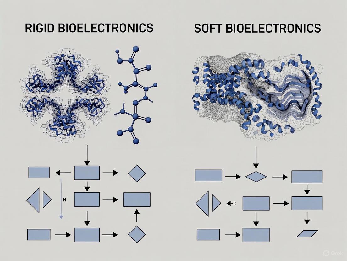
The following diagram illustrates the logical relationship and decision-making process for selecting between rigid and soft bioelectronic paradigms based on application requirements.
The choice between rigid and soft bioelectronics is not merely a material selection but a fundamental design paradigm that dictates device performance and biocompatibility. Rigid bioelectronics, with their mature fabrication and robust interfaces, remain suitable for applications where mechanical mismatch is less critical. However, the future of bioelectronics, particularly for long-term, chronic, and patient-friendly interfaces, is unequivocally soft, flexible, and stretchable. The experimental data confirms that advanced soft materials can now achieve electrical performance on par with or superior to rigid standards, while simultaneously offering unparalleled mechanical compatibility. As research continues to enhance the durability, scalability, and multifunctionality of these soft systems, they are poised to become the dominant platform for next-generation wearable, implantable, and closed-loop bioelectronic medicines.
The field of bioelectronic medicine has undergone a profound transformation, shifting from rigid, bulky implants to soft, conformable systems that better integrate with biological tissues. This evolution represents a fundamental rethinking of how electronic devices interact with the living body, moving from a paradigm of mechanical dominance to one of mechanical compatibility.
Early bioelectronic implants were constructed from rigid materials like metals and silicon, which provided operational stability but created significant mechanical mismatch with soft, dynamic biological tissues [1]. This mismatch often led to inflammatory responses, tissue damage, and eventual device failure [10]. The recognition of these limitations spurred innovation in materials science and device engineering, leading to the development of soft bioelectronics that emulate the mechanical properties of biological tissues [11].
This comparison guide examines the performance differences between rigid and soft bioelectronic systems through the lens of historical evolution, providing researchers and drug development professionals with objective data on how this technological shift has impacted device functionality, longevity, and integration with biological systems.
Material Properties and Mechanical Compatibility
The core distinction between historical and contemporary bioelectronics lies in their fundamental material properties. Traditional implants utilized materials with mechanical characteristics drastically different from biological tissues, while modern approaches prioritize mechanical compatibility.
Table 1: Material Properties Comparison Between Rigid and Soft Bioelectronics
| Property | Rigid Bioelectronics | Soft & Flexible Bioelectronics |
|---|---|---|
| Typical Material Types | Silicon, metals, ceramics | Polymers, elastomers, hydrogels, thin-film materials, meshes [1] |
| Young's Modulus | > 1 GPa | 1 kPa – 1 MPa (typically) [1] |
| Bending Stiffness | > 10⁻⁶ N·m | < 10⁻⁹ N·m [1] |
| Device Thickness | > 100 µm | < 100 µm [1] |
| Stretchability | < 1% (brittle) | > 10% (> 100% for ultra-soft devices) [1] |
The mechanical mismatch between traditional rigid implants (Young's modulus > 1 GPa) and soft neural tissue (~1–30 kPa) is profound, differing by several orders of magnitude [11]. This discrepancy prevents rigid devices from conforming to biological substrates, leading to signal instability and physical damage to neural tissue during insertion and from tissue micromotion during indwelling [11].
Soft bioelectronics address this fundamental challenge through various innovative approaches. Hydrogels have emerged as ideal interface materials due to their high water content, low modulus, and excellent biocompatibility, bridging the gap between hard electronics and soft tissues [5]. Softening implantable bioelectronics represent another advanced strategy, utilizing stiffness-tunable materials that transition from an initial rigid state for surgical implantation to a softened state inside the body, combining the advantages of both rigid and soft devices [10].
Performance Comparison and Experimental Data
The transition from rigid to soft bioelectronics has produced measurable differences in device performance, particularly regarding tissue integration, signal fidelity, and long-term stability. The following experimental data, synthesized from multiple studies, illustrates these critical performance differences.
Table 2: Performance Comparison of Rigid vs. Soft Bioelectronic Systems
| Performance Parameter | Rigid Bioelectronics | Soft Bioelectronics | Experimental Evidence |
|---|---|---|---|
| Tissue Integration & Foreign Body Response | Stiffness mismatch causes inflammation and fibrotic encapsulation [1] | Soft, conformal materials match tissue mechanics and reduce immune response [1] | e-dura implant: No significant difference in activated astrocytes/microglia vs. sham after 6 weeks in rat spinal cords [11] |
| Chronic Signal Recording Stability | Long-term degradation due to micromotion and scar tissue [1] | Better chronic signal due to stable tissue contact [1] | NeuroGrid: Stable detection of single-cell action potentials from rat brain surface for up to 10 days [11] |
| Electrode-Tissue Interface Impedance | Increasing impedance over time due to fibrotic encapsulation | Stable low impedance due to conformal contact | PEDOT:PSS-based devices: Maintain lower impedance and enhanced charge transfer capability [11] |
| Mechanical Compliance in Dynamic Environments | Brittle under strain, poor strain tolerance [1] | Stretchable and bendable; can tolerate body movement [1] | Ultrathin neuron-like electrodes: Bending stiffness ~1.4–5.7×10⁻¹⁶ N·m², comparable to axons [11] |
Experimental Protocols for Assessing Bioelectronic Performance
To generate the comparative data presented in Table 2, researchers employ standardized experimental protocols across several key domains:
Histological Analysis of Foreign Body Response:
- Methodology: Implants are surgically inserted into target tissues (e.g., brain cortex, spinal cord) of animal models. After predetermined intervals (e.g., 2, 6, 12 weeks), tissue is harvested, sectioned, and stained for immune cell markers (e.g., Iba1 for microglia, GFAP for astrocytes) [11].
- Quantification: Immunohistochemical images are analyzed to quantify the density and activation state of immune cells within a defined radius (e.g., 100 µm) from the implant-tissue interface. Reduced glial activation indicates improved biocompatibility.
- Application: This protocol was used to evaluate the e-dura spinal implant, which showed minimal immune activation comparable to sham surgery [11].
Electrophysiological Recording Stability Assessment:
- Methodology: Devices are implanted in relevant animal models (e.g., rodents, non-human primates). Neural signals (local field potentials, single-unit, multi-unit activity) are recorded periodically over weeks or months [11].
- Quantification: Signal-to-noise ratio (SNR) and electrode impedance are tracked over time. The number of viable recording channels and amplitude of detectable neural signals are measured. Stable or improving metrics indicate better tissue integration.
- Application: NeuroGrid arrays demonstrated this capability by maintaining single-neuron resolution recordings from the cortical surface for extended periods [11].
Mechanical Compliance Testing:
- Methodology: The flexural rigidity of devices is quantified using cantilever bending tests or similar mechanical measurements. For in vivo validation, devices are subjected to simulated biological environments (cyclic stretching, immersion in physiological solutions) while monitoring electrical functionality [10].
- Quantification: Bending stiffness is calculated in N·m². Devices with values approaching neural structures (∼5.9–7.6×10⁻¹⁶ N·m² for axons) demonstrate superior mechanical compatibility [11].
Visualization of the Evolutionary Pathway
The transition from rigid to soft bioelectronics follows a logical progression driven by the need for improved integration and reduced foreign body response. The following diagram illustrates this evolutionary pathway and the key technological innovations at each stage.
Figure 1: The evolutionary pathway from rigid to soft bioelectronics, highlighting key technological developments at each stage. This progression addresses the fundamental challenge of mechanical mismatch through increasingly sophisticated material and design strategies.
The Scientist's Toolkit: Essential Research Reagents and Materials
Developing and testing next-generation soft bioelectronics requires specialized materials and characterization tools. The following table details key research reagents and their functions in advancing soft, conformable bioelectronic systems.
Table 3: Essential Research Materials for Soft Bioelectronics Development
| Material/Reagent | Category | Primary Function | Application Examples |
|---|---|---|---|
| PDMS (Polydimethylsiloxane) | Elastomer | Flexible substrate/encapsulation; provides mechanical compliance [11] | e-dura spinal implants, various flexible electrode arrays [11] |
| PEDOT:PSS | Conductive Polymer | Reduces electrode impedance; enhances charge injection capacity [11] | NeuroGrid surface electrodes, neural probe coatings [11] |
| Hydrogels | Polymer Network | Tissue-like interface material; high water content enables biocompatibility [5] | Soft bioelectronic interfaces, drug-eluting matrices [5] |
| Parylene-C | Polymer | Thin-film encapsulation and insulation; provides moisture barrier [11] | Flexible neural probes, implantable sensor coatings |
| Liquid Metal Alloys | Conductive Material | Stretchable conductors for extreme deformations [10] | Stretchable interconnects, soft circuit patterns |
| Silk Fibroin | Bioresorbable Polymer | Temporary stiffener for implantation; dissolves in body [10] | Sacrificial support layer for ultra-soft devices |
The historical evolution from rigid to soft, conformable bioelectronic systems represents a paradigm shift in how we interface technology with biological organisms. The performance data clearly demonstrates that soft bioelectronics offer significant advantages in reducing foreign body response, improving long-term signal stability, and enabling seamless integration with dynamic biological tissues.
While rigid implants provided the foundation for bioelectronic medicine and remain suitable for certain applications, the future direction of the field is firmly oriented toward soft, flexible, and intelligent material systems [1]. Emerging approaches—including biohybrid interfaces that incorporate living cellular components and "smart" encapsulation systems that respond to their biological environment—promise to further blur the boundary between artificial devices and natural tissues [11].
For researchers and drug development professionals, this evolutionary pathway offers important insights: success in bioelectronic medicine increasingly depends on addressing mechanical compatibility with the same rigor as electrical performance. The continued convergence of materials science, biology, and electrical engineering will undoubtedly yield even more sophisticated biointegrated systems capable of chronic, high-fidelity interaction with the nervous system and other electrically active tissues.
The interface between bioelectronic devices and biological tissues represents one of the most critical frontiers in medical technology development. The mechanical mismatch between conventional rigid electronic materials and soft, dynamic biological tissues poses a fundamental challenge that impacts device performance, tissue integration, and long-term stability [1] [12]. This mechanical disparity—where traditional electronics possess Young's moduli in the gigapascal range (≥1 GPa) while biological tissues such as neural tissue exhibit moduli in the kilopascal range (1-10 kPa)—creates a significant mechanical incompatibility that can lead to inflammation, fibrotic encapsulation, tissue damage, and eventual device failure [2] [13].
The evolution of bioelectronics has witnessed a paradigm shift from rigid to soft, compliant systems that better mimic the mechanical properties of biological tissues [1] [12]. This transition is driven by growing evidence that mechanical compatibility is equally as important as electrical performance for chronic implantation and reliable signal acquisition. While rigid implants like silicon-based Michigan probes and Utah arrays have enabled valuable neuroscientific discoveries, their stiff nature inevitably triggers foreign body responses that degrade signal quality over time through glial scar formation [2] [13]. The emerging generation of soft bioelectronics aims to overcome these limitations through innovations in materials science, structural design, and fabrication techniques that prioritize mechanical harmony with biological systems.
Quantitative Comparison: Rigid vs. Soft Bioelectronics
The performance differences between rigid and soft bioelectronics can be quantified across multiple parameters critical to long-term functionality. The table below summarizes key comparative metrics based on current research findings.
Table 1: Performance Comparison of Rigid vs. Soft Bioelectronics
| Performance Parameter | Rigid Bioelectronics | Soft Bioelectronics | Experimental Evidence |
|---|---|---|---|
| Young's Modulus | >1 GPa (Silicon: ~10² GPa; Platinum: ~10² MPa) [2] [13] | 1 kPa - 1 MPa [1] | Material testing systems (e.g., tensile testers, nanoindenters) |
| Bending Stiffness | >10⁻⁶ Nm [1] | <10⁻⁹ Nm [1] | Cantilever bending tests, optical measurement of deformation |
| Chronic Signal Stability | Signal degradation over weeks/months due to inflammation and glial scarring [2] | Stable recording with <3% variation after 1000 bending cycles in DNA-based sensors [14] | Long-term electrophysiological recording in animal models |
| Inflammatory Response | Significant fibrotic encapsulation; chronic inflammation [2] [13] | Minimal immune response; reduced fibrotic encapsulation [1] [12] | Histological analysis (e.g., staining for astrocytes, microglia) |
| Tissue Integration | Poor integration due to stiffness mismatch; micromotion damage [2] | Conformal contact; seamless integration with tissues [1] [15] | Microscopy analysis of tissue-device interface |
| Stretchability | <1% (brittle) [1] | >10% (>100% for ultra-soft devices) [1] | Uniaxial/tensile strain testing |
| Electrical Performance under Deformation | Performance degradation or failure under strain | Maintains conductivity even at >1,200% strain for liquid metal devices [16] | Resistance measurement during mechanical deformation |
Material Strategies and Structural Designs for Mechanical Compatibility
Advanced Material Solutions
Innovative materials form the foundation of next-generation soft bioelectronics. Liquid metal-based composites, particularly gallium-based alloys, have emerged as promising conductors due to their exceptional deformability while maintaining high electrical conductivity. Recent research has demonstrated liquid metal circuits patterned with micrometer-scale precision that maintain consistent electrical performance even when stretched by more than 1,200% [16]. The combination of colloidal self-assembly and micro-transfer printing enables the creation of these highly precise and stretchable electronic networks that conform seamlessly to biological tissues [16].
Porous architectures represent another strategic approach to enhancing mechanical compatibility and biological integration. These structures facilitate bidirectional communication between human organs and their surrounding microenvironments by allowing sweat evaporation, heat dissipation, moisture transport, and biochemical diffusion [15]. Fabrication techniques such as electrospinning produce nanofiber substrates with high porosity, gas permeability, and minimal bending stiffness, enabling conformal contact with curvilinear biological surfaces without impeding natural processes like wound healing [14] [15]. These porous conductive materials can be synthesized through both top-down approaches (laser engraving, etching, photolithography) and bottom-up approaches (electrospinning, 3D printing, phase separation) [15].
Structural Engineering Innovations
Beyond material composition, structural design plays a crucial role in achieving mechanical compatibility. Serpentine patterns, mesh structures, and kirigami/origami-inspired designs enable otherwise non-stretchable materials to accommodate significant deformation [6]. These engineered structures allow conventional conductive materials like gold and platinum to be incorporated into stretchable devices without compromising electrical performance [6].
The integration of nanomesh electrodes and island-bridge architectures further enhances mechanical compliance while maintaining reliable electrical functionality. In island-bridge designs, rigid functional components (islands) are interconnected with stretchable conductors (bridges), localizing strain to the compliant interconnects while protecting active elements from mechanical stress [3]. This approach enables the incorporation of semiconductor devices that would otherwise be incompatible with soft, deformable systems.
Experimental Protocols for Assessing Tissue-Device Interface
Mechanical Compliance Testing
Protocol 1: Bending Stiffness Measurement
- Objective: Quantify the flexibility of bioelectronic devices to evaluate their compatibility with dynamic biological tissues.
- Methodology:
- Fabricate devices on substrates of varying thickness (typically <100 μm for flexible devices) [1]
- Mount samples as cantilevers and apply controlled forces at free ends
- Measure deflection using optical methods (e.g., laser displacement sensors)
- Calculate bending stiffness (D) using the formula: D = E×I, where E is Young's modulus and I is the second moment of area
- Key Parameters: Device thickness, elastic modulus of constituent materials, neutral mechanical plane position
- Validation: Ultrathin devices (<10 μm) demonstrate bending stiffness below 10⁻⁹ Nm, enabling van der Waals-driven conformal contact without adhesives [3]
Protocol 2: Cyclic Strain Testing
- Objective: Evaluate device performance under repeated deformation mimicking natural body movements.
- Methodology:
- Mount devices on stretchable substrates or mechanical testers
- Apply cyclic strain (typically 10-30% for skin-worn devices, higher for cardiac applications)
- Monitor electrical continuity, impedance, and signal quality throughout cycles
- Perform microscopic analysis to identify mechanical failure points
- Endpoint Analysis: Devices should maintain functionality with <5% variation in electrical properties after thousands of cycles [14]
Biological Integration Assessment
Protocol 3: Histological Evaluation of Foreign Body Response
- Objective: Quantify tissue reaction to implanted devices and correlate with mechanical properties.
- Methodology:
- Implant devices in animal models (typically rodents for neural interfaces)
- After predetermined periods (2, 4, 8, 12 weeks), perfuse and section tissue
- Stain for astrocytes (GFAP), microglia (Iba1), and neurons (NeuN)
- Quantify cell densities and distribution relative to implant site
- Metrics: Fibrotic capsule thickness, neuronal density in proximity, activation state of immune cells
- Findings: Rigid implants typically show 50-100 μm fibrotic encapsulation with significant neuronal loss, while soft devices exhibit minimal encapsulation [2] [13]
Protocol 4: Chronic Electrophysiological Recording Stability
- Objective: Assess long-term signal acquisition capabilities in functioning systems.
- Methodology:
- Implant recording devices in relevant brain regions
- Record neural signals (single-unit, multi-unit, local field potentials) regularly over months
- Track signal-to-noise ratio, unit yield, and amplitude stability
- Correlate electrophysiological changes with histological findings
- Validation: Soft neuroprobes maintain stable single-unit recording for >6 months, while rigid devices typically show significant signal degradation within weeks [2]
Table 2: Research Reagent Solutions for Tissue-Device Interface Studies
| Reagent/Material | Function | Example Application |
|---|---|---|
| Liquid Metal (Ga-based alloys) | Deformable conductor | Stretchable interconnects, conformal electrodes [16] |
| PEDOT:PSS | Conductive polymer | Organic electrochemical transistors (OECTs), low-impedance coatings [3] |
| Electrospun PAN/TPU nanofibers | Porous substrate | Breathable biosensing patches, wound monitoring [14] |
| Tetrahedral DNA (TDNA) | Mechanically stable biosensing element | Protein detection with reduced biofouling [14] |
| Carbon nanotubes/Graphene | Conductive nanomaterial | Strain sensors, transparent electrodes [6] |
| Self-healing polymers | Autonomous damage repair | Extended device longevity in dynamic environments [6] |
| Hydrogels | Hydrated, tissue-mimicking matrix | Injectable electronics, drug-eluting interfaces [1] |
Signaling Pathways in Foreign Body Response
The biological response to implanted devices follows a complex cascade of signaling events that initiate with mechanical mismatch and culminate in functional isolation of the device. The diagram below illustrates key pathways in this process.
Diagram 1: Foreign Body Response Signaling Pathways. The diagram contrasts the biological responses triggered by mechanically mismatched devices (red/orange) versus soft, compliant interfaces (green).
Application-Specific Performance Analysis
Neural Interfaces
The impact of mechanical mismatch is particularly pronounced in neural interfacing applications, where devices must integrate with exceptionally soft and sensitive tissues. Conventional rigid neural probes (Young's modulus ~10² GPa) create a significant mechanical mismatch with brain tissue (Young's modulus ~1-10 kPa), leading to chronic inflammation, glial scarring, and signal degradation over time [2] [13]. The foreign body response begins with immediate tissue damage during insertion, followed by persistent micromotion-induced inflammation as the device moves within the brain parenchyma. This triggers activation of microglia and astrocytes, creating a protective but electrically insulating glial scar that progressively isolates the electrode from nearby neurons, diminishing recording quality and stimulation efficacy [13].
In contrast, flexible neural probes fabricated from compliant polymers or ultra-thin silicon demonstrate significantly reduced foreign body responses. Devices with bending stiffness below 10⁻⁹ Nm promote minimal astrocyte activation and maintain proximity to neurons, enabling stable single-unit recording over extended periods [2]. Advanced approaches include mesh electronics that seamlessly integrate with neural tissue through designed porosity and mechanical properties matching the extracellular matrix. These systems have demonstrated reliable tracking of the same individual neurons for over a year, far surpassing the capabilities of rigid interfaces [2].
Cardiac Monitoring and Stimulation
The dynamic nature of cardiac tissue presents unique challenges for bioelectronic interfaces. Traditional cardiac catheters and pacemakers utilize relatively rigid components that can cause tissue damage, particularly in continuously contracting heart muscle. Recent innovations in soft bioelectronics address these limitations through compliant designs that maintain stable contact during cardiac cycles.
Instrumented balloon catheters integrated with liquid metal microelectrode arrays represent a significant advancement in this domain. These devices can expand without compromising electrical conductivity, providing high-resolution maps of cardiac electrical activity during procedures such as ablation therapy [16]. Laboratory and animal tests demonstrate that these compliant systems maintain low electrical impedance while conforming to the endocardial surface, offering more detailed electrophysiological data than conventional rigid catheters [16]. The enhanced contact stability improves signal quality and enables more precise identification of arrhythmic substrates.
Chronic Wound Monitoring
The monitoring of chronic wounds requires specialized biointerfaces that can conform to irregular wound beds without impeding the healing process. Traditional rigid sensors often hinder exudate management and gas exchange, potentially exacerbating wound complications. Soft, breathable biosensing patches address these limitations through porous nanofiber substrates that permit moisture vapor transmission while maintaining conformal contact [14].
Advanced wound monitoring platforms incorporate both biophysical sensors (temperature, pH, impedance) and biochemical sensors for detecting low-abundance protein biomarkers indicative of healing status. The integration of self-confined tetrahedral DNA circuits (SCTD) enables sensitive detection of inflammatory cytokines (TNF-α, IL-6) and growth factors (TGF-β1, VEGF) with minimal signal attenuation (<8% over 4 weeks) despite mechanical deformation [14]. These systems demonstrate mechanical stability within 3% variation after 1000 bending cycles, making them suitable for monitoring wounds over articulating joints or other dynamic areas [14].
The critical role of mechanical matching at the tissue-device interface is now unequivocally established, driving a fundamental shift toward soft, compliant bioelectronic systems. Quantitative evidence demonstrates that mechanical compatibility directly correlates with improved signal stability, reduced foreign body response, and extended functional longevity across diverse applications from neural interfaces to cardiac monitoring and wound management. The ongoing development of novel materials—including liquid metal composites, conductive polymers, and porous architectures—combined with innovative structural designs continues to advance the capabilities of soft bioelectronics.
Future research directions will likely focus on further enhancing the biological integration of these devices through biohybrid approaches incorporating living cellular components, dynamic materials capable of adapting their properties in response to physiological changes, and increasingly sophisticated closed-loop systems that combine monitoring and therapeutic intervention. As the field progresses, standardized methodologies for assessing mechanical compatibility and biological response will become increasingly important for comparative evaluation of emerging technologies. The ultimate convergence of materials science, biology, and engineering will enable a new generation of bioelectronic medicines that seamlessly interface with the human body, transforming the management of chronic diseases and neurological disorders.
Inherent Advantages and Limitations of Each Approach
The field of bioelectronic medicine leverages miniaturized electronic devices to interface with the body's electrically active tissues, offering innovative therapeutic solutions distinct from traditional pharmaceuticals [1]. A central paradigm in the development of these devices is the choice between rigid and soft material platforms. Conventional bioelectronics have primarily been constructed from rigid materials such as metals and silicon, valued for their mechanical stability and robust electrical performance [10]. However, the inherent mechanical mismatch between these stiff devices and soft, dynamic biological tissues often leads to complications, including inflammation, scar tissue formation, and long-term signal degradation [2] [17].
In response, the field has seen a significant shift toward soft and flexible bioelectronics, which aim to emulate the mechanical properties of biological tissues [1] [10]. This review provides a structured, objective comparison of these two approaches, dissecting their inherent advantages and limitations. By synthesizing current research and experimental data, we aim to offer researchers, scientists, and drug development professionals a clear framework for selecting the appropriate material platform for specific biomedical applications, from neural interfacing and cardiac pacemaking to wearable health monitoring.
Performance Comparison: Rigid vs. Soft Bioelectronics
The fundamental differences in material composition between rigid and soft bioelectronics directly translate to distinct performance characteristics in biological environments. The table below summarizes a comparative analysis of their key properties.
Table 1: Comparative Analysis of Rigid and Soft Bioelectronics
| Property | Rigid Bioelectronics | Soft Bioelectronics |
|---|---|---|
| Typical Material Types | Silicon, metals, ceramics [1] | Polymers, elastomers, hydrogels, thin-film materials, meshes [1] [17] |
| Young's Modulus | > 1 GPa [1] | 1 kPa – 1 MPa (typically) [1] |
| Bending Stiffness | > 10⁻⁶ Nm [1] | < 10⁻⁹ Nm [1] |
| Stretchability | < 1% (brittle) [1] | > 10% (> 100% for ultra-soft devices) [1] |
| Tissue Integration & Biocompatibility | Disadvantage: Stiffness mismatch causes inflammation and fibrotic encapsulation [1] [2] | Advantage: Soft, conformal materials match tissue mechanics and reduce immune response [1] [10] |
| Chronic Signal Fidelity | Disadvantage: Long-term degradation due to micromotion and scar tissue [1] [2] | Advantage: Better chronic signal due to stable tissue contact and reduced scarring [1] [7] |
| Implantation & Surgical Handling | Advantage: Rigid housing eases handling during implantation [1] [10] | Disadvantage: May require new surgical techniques or temporary stiffeners [1] [10] |
| Power/Data Interfaces | Advantage: Mature, robust wired and wireless interface options [1] | Disadvantage: Interfaces can be less robust; an area of ongoing development [1] |
Experimental Protocols for Performance Validation
To quantitatively compare the performance of rigid and soft bioelectronics, researchers employ standardized experimental protocols. The workflows below outline two critical tests for evaluating bioelectronic devices.
Protocol for Electrode-Tissue Interface Impedance
Electrode-tissue interface impedance is a critical metric for assessing signal acquisition quality and stimulation efficiency. Lower impedance is generally associated with better signal-to-noise ratio (SNR) for recording and more efficient charge transfer for stimulation [7].
Protocol for Chronic In Vivo Biocompatibility
Assessing the chronic foreign body response is essential for evaluating the long-term stability and safety of an implant. The formation of fibrotic scar tissue around an implant can severely compromise its function [1] [2].
The Scientist's Toolkit: Key Research Reagents and Materials
The development and testing of bioelectronics rely on a specialized set of materials and reagents. The following table details essential items used in the featured experiments and broader field research.
Table 2: Key Research Reagent Solutions for Bioelectronics Development
| Reagent/Material | Function & Application | Key Characteristics |
|---|---|---|
| PEDOT:PSS | An intrinsically conductive polymer used to create conductive hydrogels for neural interfaces [17]. | High conductivity (~40 S/cm to 670 S/cm), biocompatible, can form soft hydrogels with low Young's modulus [17]. |
| Liquid Metals (e.g., Ga-based) | Used to create stretchable and self-healing electrodes for wearable and implantable devices [7] [10]. | High conductivity, fluidic at room temperature, enabling extreme stretchability and conformability to skin [7]. |
| Conductive Hydrogel Nanocomposites | Soft, tissue-like materials for implantable electrodes, combining hydrogels with conductive nanofillers [17]. | Tissue-mimetic softness (kPa-MPa range), ionic/electronic conductivity, often biodegradable and bioadhesive [17]. |
| Silicon (for Michigan/Utah probes) | The primary material for conventional rigid microelectrode arrays for high-density neural recording [2]. | Rigid and brittle (GPa modulus), enables high-resolution lithography, excellent short-term signal fidelity [1] [2]. |
| Ag/AgCl Electrodes | The clinical gold standard for gel-based skin electrodes, used as a benchmark in experimental protocols [7]. | Stable electrochemical potential, low noise; used as a reference for normalizing SNR and impedance data [7]. |
| Stiffness-Tunable Polymers | Polymers (e.g., PLGA, silk fibroin) used in "softening" implants that are rigid for insertion but soften in the body [10]. | Wide, tunable stiffness range (MPa to kPa); degrade or hydrate in response to bodily fluids [10]. |
Emerging Trends and Future Directions
The dichotomy between rigid and soft bioelectronics is being bridenced by innovative hybrid and adaptive technologies. One promising direction is the development of softening implantable bioelectronics that transition from a rigid state for easy surgical handling to a soft state post-implantation for enhanced biocompatibility [10]. These devices use materials like PLGA or silk fibroin that degrade, or hydrogels that swell, upon exposure to bodily fluids, dynamically reducing their modulus from GPa to kPa ranges [10].
Another frontier is the creation of multifunctional and "living" bioelectronic interfaces [2]. These systems integrate electrical recording with other modalities like optical stimulation and chemical sensing, providing a more comprehensive view of neural circuit dynamics. Furthermore, biohybrid systems that incorporate living cells or biological components within conductive scaffolds are being explored for their potential to promote neural regeneration and achieve seamless, synaptically connected integration with host tissue [2].
Despite rapid progress, challenges in manufacturing scalability, long-term encapsulation, and power management remain active areas of research [1] [7]. The continued convergence of materials science, biology, and electrical engineering will be crucial in developing next-generation bioelectronics that are not only high-performing but also stable, safe, and fully integrated with the human body for chronic applications.
The Trajectory Towards Tissue-Like Electronics
The field of bioelectronics is undergoing a fundamental transformation, moving away from rigid, bulky devices toward soft, tissue-like electronics that seamlessly integrate with biological systems. This paradigm shift is driven by the critical need to overcome the mechanical mismatch between conventional electronic materials and the soft, dynamic tissues of the human body [1]. Early bioelectronic implants, such as pacemakers and deep brain stimulators, were constructed from rigid materials like silicon and metals. While effective, their stiffness often led to patient discomfort, inflammatory responses, fibrotic encapsulation, and eventual device failure over time [1] [18].
The human body is composed of soft, curvilinear, and continuously moving tissues, making it critical for implanted and wearable devices to conform and integrate seamlessly with their biological environment [1]. This review objectively compares the performance of rigid bioelectronics against emerging soft, tissue-like alternatives, focusing on quantitative metrics essential for researchers and drug development professionals. We examine material strategies, experimental data on device performance, and detailed methodologies shaping the next generation of biomedical technologies, framing this progress within the broader thesis of rigid versus soft bioelectronics performance comparison research.
Performance Comparison: Quantitative Analysis of Rigid vs. Soft Bioelectronics
The performance disparity between traditional rigid bioelectronics and emerging soft alternatives can be quantified across multiple mechanical, electrical, and biological parameters. The tables below summarize key comparative data from recent studies.
Table 1: Material and Mechanical Property Comparison between Rigid and Soft Bioelectronics
| Property | Rigid Bioelectronics | Soft & Flexible Bioelectronics | Performance Implications |
|---|---|---|---|
| Young's Modulus | > 1 GPa [1] | 1 kPa – 1 MPa (typically) [1] | Soft devices match tissue mechanics, reducing immune response. |
| Bending Stiffness | > 10-6 Nm [1] | < 10-9 Nm [1] | Ultralow stiffness enables conformal contact without irritation. |
| Typical Device Thickness | > 100 µm [1] | < 100 µm [1] | Sub-100 µm thickness is critical for van der Waals-driven skin adhesion. |
| Stretchability | < 1% (brittle) [1] | > 10% (> 1000% for some liquid metal devices) [1] [16] | High stretchability allows operation on dynamic organs (heart, skin, intestines). |
| Typical Materials | Silicon, metals, ceramics [1] | Polymers, elastomers, hydrogels, liquid metals, thin-film meshes [1] [16] [19] | Material choice directly influences biocompatibility and device integration. |
Table 2: Functional Performance and Biocompatibility Metrics
| Parameter | Rigid Bioelectronics | Soft & Flexible Bioelectronics | Experimental Context |
|---|---|---|---|
| Chronic Signal Stability | Long-term degradation due to micromotion and scar tissue [1] | Better chronic signal due to stable tissue contact [1] | Neural recording; soft devices maintain stable single-neuron recording for up to 4 months [20]. |
| Tissue Damage & Inflammation | High risk due to stiffness mismatch [1] [3] | Significantly reduced inflammatory and immune responses [3] | Histological analysis post-implantation shows minimal fibrosis for soft devices. |
| Electrical Conductivity under Strain | Conductivity lost upon fracture | Maintains conductivity even when stretched >1200% [16] | Liquid metal-based stretchable electronics [16]. |
| Adhesion to Tissue | Requires sutures or anchors; poor innate adhesion. | Strong, conformal adhesion via van der Waals forces or bioadhesives [6] [3] | Ultrathin devices (<5 µm) achieve adhesion through van der Waals forces alone [3]. |
| Long-Term Operational Stability | Limited by fibrotic encapsulation and mechanical failure [1] | Demonstrated stability for over 43 weeks in animal models [20] | Injectable and implantable flexible fibres for bioelectrical monitoring [20]. |
The data reveals a clear trajectory: soft bioelectronics significantly outperform rigid counterparts in mechanical compatibility, long-term signal stability, and biocompatibility. The fundamental advantage lies in minimizing the modulus mismatch with native tissues, which can reduce interfacial stress and strain by over 80% through optimized energy dissipation mechanisms [19]. This mechanical harmony is a prerequisite for chronic device stability and high-fidelity signal acquisition.
Experimental Protocols for Evaluating Bioelectronic Performance
Validating the performance of tissue-like electronics requires rigorous, standardized experimental protocols. Below are detailed methodologies for key evaluations cited in this field.
Protocol 1: In Vivo Testing of Long-Term Stability and Biocompatibility
This protocol assesses the chronic performance and tissue response of implantable bioelectronic devices [20] [3].
- Objective: To evaluate the long-term signal fidelity, device stability, and histological tissue response of an implanted soft bioelectronic device over a period of several months.
- Materials:
- Test Device: Soft bioelectronic device (e.g., rolled-up fibre, hydrogel electrode).
- Animal Model: Rodents (e.g., mice or rats) or larger animals (e.g., pigs) as appropriate.
- Surgical equipment for sterile implantation.
- Data Acquisition System: For recording electrophysiological signals (e.g., neural spikes, local field potentials, ECG).
- Materials for Histology: Fixatives (e.g., paraformaldehyde), cryostat, staining agents (e.g., H&E for general morphology, immunofluorescence for specific cell markers like CD68 for macrophages).
- Procedure:
- Implantation: Surgically implant the test device into the target tissue (e.g., brain, heart, peripheral nerve) under approved anesthetic and analgesic protocols.
- Signal Recording: At regular intervals (e.g., weekly), connect the device to the data acquisition system and record target biosignals (e.g., signal-to-noise ratio of neural spikes, amplitude of ECG signals).
- Termination and Extraction: At predetermined endpoints (e.g., 4 weeks, 12 weeks, 43+ weeks), euthanize the animal and carefully extract the device along with the surrounding tissue.
- Histological Analysis:
- Fix the tissue sample for 24-48 hours.
- Process, embed, and section the tissue.
- Stain sections with H&E and relevant immunofluorescence markers.
- Image the tissue-device interface to quantify fibrotic capsule thickness and immune cell infiltration.
- Data Analysis: Compare signal quality metrics over time and correlate with histological findings. A stable signal-to-noise ratio and minimal fibrotic encapsulation indicate superior performance.
Protocol 2: Electro-Mechanical Characterization of Stretchable Conductors
This protocol quantitatively measures the electrical performance of conductive materials under mechanical deformation, a critical test for wearable and implantable sensors [16] [6].
- Objective: To characterize the resistance change of a stretchable conductive element (e.g., liquid metal microelectrode, conductive hydrogel) under uniaxial tensile strain.
- Materials:
- Sample: Fabricated stretchable conductor.
- Universal Testing Machine (UTM) equipped with a tensile stage.
- Digital Source Meter or LCR Meter.
- Custom fixtures to electrically connect the sample to the meter while stretched.
- Procedure:
- Setup: Mount the sample onto the UTM and connect its ends to the source meter using non-destructive clamps.
- Baseline Measurement: Measure the initial resistance (R0) of the sample at 0% strain.
- Strain Cycling: Program the UTM to apply a specific strain cycle (e.g., 0% to 50% strain and back, or a more extreme 0% to 1200% strain [16]).
- Simultaneous Monitoring: Continuously or at fixed strain intervals, record the sample's resistance (R) and the applied strain (ε) throughout the cycle.
- Repeat: Perform multiple cycles to assess fatigue and recovery.
- Data Analysis: Calculate the normalized resistance change (ΔR/R0). Plot ΔR/R0 against strain (ε). A minimal change in resistance, even at high strains, indicates excellent electro-mechanical stability, a hallmark of advanced materials like liquid metals.
Protocol 3: Evaluation of Conformal Contact and Signal Fidelity on Skin
This protocol tests the performance of wearable epidermal electronics [3].
- Objective: To compare the quality of electrophysiological signals (e.g., ECG, EMG) acquired by a rigid electrode, a flexible electrode, and an ultrathin, conformal electrode during subject movement.
- Materials:
- Electrode Types: (a) Standard rigid Ag/AgCl gel electrode, (b) Flexible Au/PET electrode, (c) Ultrathin electronic tattoo (e.g., graphene-based or nanomesh electrode).
- Biopotential Amplifier with multiple channels.
- Motion Tracking System or accelerometer.
- Procedure:
- Application: Apply the three different electrode types adjacently to the same skin site (e.g., chest for ECG, forearm for EMG).
- Data Recording:
- Record baseline signals while the subject is stationary.
- Instruct the subject to perform controlled movements (e.g., walking, jogging, flexing muscles).
- Simultaneously record the electrophysiological signals and motion data.
- Analysis: Calculate the signal-to-noise ratio (SNR) and identify motion artifacts in the recorded signals for each electrode type during both static and dynamic phases.
- Data Analysis: Ultrathin, conformal electrodes are expected to show significantly higher SNR and fewer motion artifacts during movement due to their superior skin-contact stability, preventing detachment and minimizing motion-induced noise.
Visualization: Material and Performance Relationships in Tissue-Like Electronics
The development of high-performing soft bioelectronics relies on the interplay between material innovation, structural design, and resulting device properties. The following diagram illustrates this logical workflow and the key performance advantages it enables.
Material-Driven Performance Workflow - This diagram illustrates the logical pathway from material and structural choices to the key performance advantages of tissue-like electronics.
The Scientist's Toolkit: Essential Research Reagents and Materials
The advancement of tissue-like electronics relies on a specific toolkit of innovative materials and reagents. The following table details key solutions and their functions for researchers in this field.
Table 3: Research Reagent Solutions for Developing Soft Bioelectronics
| Material/Reagent | Category | Key Function & Properties | Representative Applications |
|---|---|---|---|
| Liquid Metals (e.g., EGaIn) | Conductive Element | Extraordinary stretchability (>1200%) and stable conductivity under deformation; can be patterned at micrometer scale [16]. | Stretchable interconnects, balloon catheter microelectrode arrays for cardiac mapping [16]. |
| 2D Materials (e.g., Graphene, MXenes) | Conductive Element | Atomically thin, high electrical conductivity, optical transparency, and mechanical flexibility [18]. | Epidermal electronic tattoos for electrophysiological monitoring, transparent electrodes for OECTs [6] [18]. |
| Biomaterial-Based Hydrogels (Gelatin, Chitosan, Alginate) | Soft Substrate / Conductor | Tissue-matching Young's modulus, inherent biocompatibility, ionic conductivity; can be engineered with self-healing and adhesive properties [19]. | Wearable strain sensors, injectable bioelectronics, interfaces for electrophysiological signal recording and stimulation [19]. |
| Alvetex Advanced Scaffold | 3D Cell Culture Platform | Provides a porous polystyrene scaffold to engineer more physiologically relevant 3D tissue models in vitro for device testing [21]. | Creating human skin equivalents for pre-clinical testing of wearable and implantable bioelectronic devices. |
| PEDOT:PSS | Conductive Polymer | High conductivity for a polymer, biocompatibility, mixed ionic-electronic conductivity ideal for interfacing with biological tissues [3]. | Active layer in Organic Electrochemical Transistors (OECTs) for signal amplification in flexible biosensors [3]. |
| Parylene-C | Substrate/Encapsulation | Biocompatible polymer used as an ultrathin (<5 µm), flexible, and conformal substrate and protective encapsulation layer [3]. | Substrate for ultraflexible and implantable neural interfaces and epidermal electronic systems [3]. |
The trajectory towards tissue-like electronics is unequivocally charting a course away from the rigid, mechanically mismatched platforms of the past. Quantitative performance comparisons reveal that soft bioelectronics, engineered through innovations in materials and structural design, consistently outperform rigid devices in critical areas: achieving mechanical harmony with biological tissues, maintaining stable, high-fidelity signals over chronic timescales, and minimizing adverse immune responses. While challenges in large-scale manufacturing and long-term in vivo stability persist, the experimental data and protocols outlined provide a roadmap for continued progress. For researchers and drug development professionals, the adoption of these soft, conformal systems promises not only more reliable and comfortable devices for patients but also more accurate and predictive models for therapeutic development and testing. The future of bioelectronics is undoubtedly soft.
Engineering the Future: Material Innovations and Applications in Soft Bioelectronics
Conventional bioelectronic systems, typically constructed from rigid materials like silicon and metals, suffer from a fundamental mechanical mismatch with soft biological tissues. This incompatibility often leads to adverse effects such as inflammation, reduced signal transmission efficiency, and challenges in achieving stable long-term bio-integration [22]. The emergence of soft electronic materials—specifically organic semiconductors, hydrogels, and conductive polymers—represents a transformative approach to bridging this biotic-abiotic divide. These materials combine the advanced electronic functionalities of traditional semiconductors with the soft, deformable, and biocompatible properties of biological tissues, enabling a new generation of bio-integrated devices.
This guide provides a comparative analysis of these three material classes, focusing on their performance characteristics, applications, and experimental methodologies within bioelectronics research. The shift toward these soft materials is driven by the need for devices that can form conformal contact with complex tissue surfaces, minimize mechanical mismatch, and facilitate stable adhesion—all critical factors for enhancing the fidelity of signal acquisition in sensing applications and mitigating the foreign-body response [22].
Comparative Performance Analysis
The selection of materials for soft bioelectronics requires careful consideration of electronic, mechanical, and biological properties. The table below provides a quantitative comparison of key performance metrics for organic semiconductors, hydrogels, and conductive polymers.
Table 1: Performance Metrics of Soft Electronic Materials
| Material Class | Charge Carrier Mobility (cm² V⁻¹ s⁻¹) | Young's Modulus | Stretchability | Key Strengths | Major Limitations |
|---|---|---|---|---|---|
| Organic Semiconductors | Up to 1.4 (in hydrogel composites) [23] | Not specified in results | Not specified in results | • Rich electronic/optoelectronic functions (signal amplification, photoexcitation) [23] • Flexibility [24] | • Environmental sensitivity (moisture, oxygen) [24] • Limited durability [24] |
| Hydrogels | Not primarily conductive (except specialized composites) | 1 kPa - 100 kPa (tissue-like) [22] | High (e.g., 569% elongation) [22] | • Superior biocompatibility & tissue integration [22] • Tunable mechanical properties [22] | • Low electrical conductivity (native) • Environmental sensitivity (dehydration) [22] |
| Conductive Polymers | Varies with doping and type | Not specified in results | Not specified in results | • High electrical conductivity • Mechanical flexibility [25] • Ease of processing [26] | • Limited biocompatibility for some types [25] • Mechanical rigidity vs. tissues [25] |
Detailed Material Profiles and Experimental Methodologies
Organic Semiconductors
Material Profile: Organic semiconductors are carbon-based compounds, including small molecules (e.g., pentacene, rubrene) and polymers (e.g., P3HT, polyfluorenes), that possess semiconducting properties [27]. They are pivotal in applications such as organic light-emitting diodes (OLEDs), organic photovoltaics (OPVs), and organic field-effect transistors (OFETs) [24]. Their key advantage lies in enabling flexible, lightweight, and cost-effective electronic devices, which are ideal for wearable health monitors and implantable sensors [24].
Experimental Protocol: Fabrication of Hydrogel-Semiconductor Composites (hydro-SC)
A groundbreaking methodology for creating ultra-soft semiconducting hydrogels with high electronic performance has been recently developed [23].
- Solution Preparation: A mixed solution is prepared using a polymer semiconductor (e.g., p(g2T-T)) and a hydrogel-forming monomer (e.g., Acrylic Acid, AAc) in dimethyl sulfoxide (DMSO). A crosslinker and photoinitiator are added.
- Film Casting and Gelation: The solution is spin-coated or cast onto a substrate. UV-crosslinking is performed to form a 3D network of the hydrogel polymer within the DMSO solvent, creating an organogel.
- Solvent Exchange: The DMSO-swollen gel is immersed in water, exchanging the solvent. The polymer semiconductor, insoluble in water, precipitates and assembles into a percolated network within the porous hydrogel framework, forming the final hydro-SC.
- Device Fabrication and Characterization: The resulting hydro-SC can function as the channel layer in Organic Electrochemical Transistors (OECTs). Electrical performance is characterized by measuring charge-carrier mobility and transconductance, while mechanical properties like Young's modulus are assessed via tensile testing [23].
Hydrogels
Material Profile: Hydrogels are three-dimensional networks of hydrophilic polymers that can absorb and retain large amounts of water or biological fluids [28]. Their exceptional biocompatibility, tissue-like mechanical properties (modulus tunable from 1 to 100 kPa), and high water content make them ideal for bio-integration [22]. While naturally insulating, their functionality can be expanded by creating composites with conductive materials.
Experimental Protocol: Fabrication of a Dual-Network Conductive Hydrogel
A representative protocol for creating a mechanically robust and conductive hydrogel involves a one-pot method using a binary solvent system [22].
- Polymer Dissolution: Polyvinyl alcohol (PVA) is dissolved in a mixed solvent of glycerol (GL) and water. Gelatin is then added to the mixture to form a dual-network precursor.
- Gel Formation: The mixture is injected into molds and subjected to a freeze-thaw cycle (e.g., -20°C to 25°C) to physically crosslink the PVA via microcrystalline formation.
- Mechanical and Electrical Tuning: The mechanical strength and elasticity can be tuned by adjusting the glycerol content, which influences hydrogen bonding. Electrical conductivity can be imparted by incorporating ionic crosslinkers like Fe³⁺ ions during synthesis. The concentration of Fe³⁺ can be varied to optimize both electrical conductivity and mechanical toughness [22].
- Performance Testing: The resulting hydrogel's tensile strength, elongation at break, and toughness are measured. Electrical performance can be demonstrated by testing its ability to complete a simple circuit, such as powering an LED [22].
Conductive Polymers
Material Profile: Conductive polymers are organic polymers with a conjugated π-electron backbone that, upon doping, exhibit significant electrical conductivity [25]. Key examples include poly(3,4-ethylenedioxythiophene) (PEDOT), polypyrrole (PPy), and polyaniline (PANI) [25]. They combine the electronic properties of metals with the processing advantages and flexibility of plastics, making them widely used in biosensing, neural interfaces, and energy storage [25].
Experimental Protocol: Creating an Injectable Conductive Polymer Formulation for Drug Delivery
Recent advances allow conductive polymers to be formulated for minimally invasive delivery and seamless tissue integration [25].
- Polymer Synthesis and Functionalization: A conductive polymer like PPy or PEDOT is synthesized or obtained commercially. To improve biocompatibility and processability, it may be chemically functionalized or blended with biocompatible polymers (e.g., PSS for PEDOT:PSS).
- Formulation for Injectability: The conductive polymer is processed into an injectable form. This can involve creating a suspension of polymer nanoparticles in a biocompatible aqueous buffer or formulating a conductive hydrogel composite that is shear-thinning.
- Drug Loading: Therapeutic agents or biomolecules are loaded into the polymer matrix. This can be achieved through absorption, electrochemical entrapment during synthesis, or covalent attachment.
- Stimulation-Triggered Release: The loaded formulation is injected into the target tissue. The release of the therapeutic agent is triggered by applying an electrical stimulus. The resulting current or redox state change in the polymer induces the controlled release of the drug, enabling localized and on-demand therapy [25].
The Scientist's Toolkit: Essential Research Reagents
Table 2: Key Reagents and Materials for Soft Bioelectronics Research
| Item | Function/Application | Representative Examples |
|---|---|---|
| Polymer Semiconductors | Forms the active semiconductor layer in transistors and sensors [23]. | p(g2T-T), Poly(3-hexylthiophene) (P3HT) [27] [23] |
| Hydrogel Forming Monomers/Polymers | Creates the hydrophilic, soft matrix for bio-integration [22] [23]. | Acrylic Acid (AAc), Polyvinyl Alcohol (PVA), Gelatin, Poly(ethylene glycol) diacrylate (PEGDA) [22] [23] |
| Conductive Polymers | Provides electrical conductivity for electrodes, sensors, and stimulation [25]. | PEDOT:PSS, Polypyrrole (PPy), Polyaniline (PANI) [25] |
| Crosslinkers | Stabilizes the 3D network of hydrogels and composites. | N,N'-Methylenebis(acrylamide), Fe³⁺ ions [22] |
| Biocompatible Solvents | Processing medium for material synthesis and fabrication. | Dimethyl Sulfoxide (DMSO), Water [23] |
| Dopants | Enhances the electrical conductivity of conjugated polymers. | Choline chloride, Tosylate ions [25] |
Research Workflow and Material Interrelationships
The following diagram illustrates the experimental workflow for developing and characterizing a soft bioelectronic material, such as a hydrogel-semiconductor composite, integrating the key protocols and characterization steps outlined in this guide.
Experimental Workflow for Soft Bioelectronics
The comparative analysis presented in this guide underscores that organic semiconductors, hydrogels, and conductive polymers each occupy a unique and complementary niche in the soft bioelectronics landscape. The future of the field lies not in the supremacy of a single material, but in the strategic integration of these materials into hybrid systems that leverage their collective strengths. Examples include hydrogel-semiconductor composites for high-sensitivity biosensing and conductive polymer-laden hydrogels for injectable, multifunctional neural interfaces [22] [23].
Future advancements will be driven by several key trends: the development of high-performance, environmentally stable organic semiconductors; the refinement of AI-driven design and 4D-bioprinting techniques for fabricating intelligent hydrogel scaffolds [28]; and the ongoing pursuit of enhanced biocompatibility and long-term stability in conductive polymers [25]. As these material innovations converge, they will continue to blur the lines between electronics and biology, enabling a new era of diagnostic and therapeutic devices that are seamlessly and symbiotically integrated with the human body.
The evolution of bioelectronics from rigid to soft constructs represents a paradigm shift in medical device technology. Traditional rigid implants, composed of materials like silicon and metals with a Young's modulus exceeding 1 GPa, exhibit significant mechanical mismatch with biological tissues (typically in the kPa range), leading to inflammation, fibrosis, and eventual device failure [1] [2]. This mechanical mismatch hinders conformal contact, causing poor signal quality and tissue damage during movement [29] [30]. Soft bioelectronics address these limitations through innovative structural designs that enable flexibility and stretchability while maintaining high electronic performance. Among these strategies, three principal architectural approaches have emerged: ultra-thin films, mesh geometries, and serpentine structures. This guide provides a comparative analysis of these designs, focusing on their mechanical resilience, electrical stability, and performance in biomedical applications, to inform researchers and development professionals in their selection of appropriate interface technologies.
Structural Design Fundamentals and Comparative Performance
Ultra-Thin Films
Design Principle: Ultra-thin films reduce bending stiffness by minimizing device thickness to the micrometer or sub-micrometer scale, enabling flexibility through minimal mechanical cross-section [31] [32]. This approach allows conventional rigid electronic materials to conform to curved biological surfaces.
Fabrication Methodology: Typically involves deposition and patterning of thin metal films (e.g., gold, platinum) or silicon membranes on flexible substrates like polyimide (PI) or parylene using photolithography and etching processes [29] [32]. Silicon-on-insulator (SOI) technologies facilitate the creation of hyperflexible silicon-based thin-film membranes with nanometer-scale structural dimensions [29].
Performance Characteristics: Devices with thicknesses below 100 µm achieve significantly reduced bending stiffness (< 10⁻⁹ Nm), enabling conformal contact with tissues [1]. However, a significant drawback is their compromised mechanical robustness and handling difficulty [31]. Thin films also have limited inherent stretchability and may suffer from fatigue failure under repetitive cyclic loading [32].
Mesh Geometries
Design Principle: Mesh geometries incorporate interconnected networks of conductive traces with strategically placed openings, distributing mechanical strain across the structure and enhancing both flexibility and permeability [29] [33]. These designs are categorized mainly as open-mesh and closed-mesh configurations.
Fabrication Methodology: Fabricated using laser cutting or photolithographic patterning of metal-coated polymer substrates (e.g., gold on polyimide) [33]. Advanced manufacturing techniques like 3D printing enable sophisticated mesh module designs [29].
Performance Characteristics: A comparative study evaluating gold-coated polyimide mesh electrodes under standardized bending and stretching tests revealed distinct performance differences between open-mesh and closed-mesh designs [33]. The table below summarizes quantitative findings from this controlled comparison, where all designs had consistent conductive area (50%), trace width (0.8 mm), and overall dimensions (11.21 mm × 11.21 mm).
Table 1: Performance Comparison of Mesh Electrode Geometries under Mechanical Strain
| Performance Metric | Open-Mesh Design | Closed-Mesh Design |
|---|---|---|
| Resistance Variation under Strain | Higher variation due to longer current paths and sparse material distribution [33] | Lower variation; more stable due to denser conductive network [33] |
| Signal-to-Noise Ratio (SNR) in EMG | Lower SNR | Highest SNR (up to 14.83 dB) with minimal motion artifacts [33] |
| Handling Motion Artifacts | Better for handling motion artifacts due to high flexibility [33] | Balanced performance across various strains [33] |
| Stretchability | Maximizes stretchability and surface conformity [33] | Provides moderate stretchability with electrical stability [33] |
Serpentine Structures
Design Principle: Serpentine structures utilize wavy, horseshoe-like meandering traces to accommodate applied strain through in-plane bending, twisting, and out-of-plane buckling rather than material stretching [33] [32]. This design localizes deformation away from sensitive active components.
Fabrication Methodology: Achieved through photolithographic patterning of metal traces on elastomeric substrates (e.g., PDMS, Ecoflex) or as interconnects in island-bridge configurations [29] [32]. The island-bridge architecture utilizes rigid electrode islands connected by soft, stretchable serpentine bridges, effectively decoupling mechanical and electrical strain [33].
Performance Characteristics: Serpentine interconnects demonstrate exceptional ability to withstand substantial mechanical deformation. Research shows that vertical serpentine structures fabricated on silicon platforms can withstand up to 350% strain while maintaining electrical stability, with less than a 2% change in electrical resistance under 300% strain [32]. The island-bridge design incorporating serpentine interconnects shows the lowest resistance variation (±1.61%) under standardized testing [33]. However, limitations include space inefficiency due to the required meandering paths, which reduces functional density, and potential strain concentration at the bridge interfaces in island-bridge designs [33] [32].
Table 2: Comprehensive Comparison of Structural Flexibility Designs
| Design Characteristic | Ultra-Thin Films | Mesh Geometries | Serpentine Structures |
|---|---|---|---|
| Primary Mechanism | Reduced bending stiffness via minimal thickness [31] | Strain distribution through porous network [33] | Strain accommodation through meandering traces [32] |
| Typical Materials | Thin metals, silicon membranes on polyimide [29] | Gold-coated polyimide, laser-cut polymers [33] | Gold, copper on elastomers; silicon with PI encapsulation [32] |
| Effective Strain Range | Limited inherent stretchability | Open-mesh: High; Closed-mesh: Moderate [33] | Very high (up to 350% demonstrated) [32] |
| Electrical Stability under Strain | Moderate | Closed-mesh: High stability; Open-mesh: Lower stability [33] | Very high (minimal resistance variation) [33] |
| Functional Density | High | Moderate (reduced by openings) | Low to moderate (space-inefficient) [32] |
| Fabrication Complexity | Moderate | Low to moderate | High (particularly for 3D architectures) [32] |
| Ideal Application Context | Flexible but minimally-stretched interfaces [31] | Conformal surfaces with moderate movement; EMG sensing [33] | High-stretch environments; Interconnects between rigid islands [33] |
Experimental Protocols for Performance Validation
Mechanical Reliability Testing
Cyclic Bending Test Protocol: Electrode samples are mounted on a motorized stage that induces repeated bending at a specified radius (e.g., 5mm bend radius). Resistance is continuously monitored throughout thousands of cycles (typically 10,000+ cycles) to assess mechanical fatigue resistance. Testing should be performed at frequencies simulating physiological movements (e.g., 1-2 Hz for joint motion) [33].
Uniaxial Stretching Test Methodology: Samples are clamped in a tensile testing system and subjected to controlled strain levels (e.g., 10-30%) while measuring electrical resistance in real-time. The strain is applied cyclically at physiological relevant rates. The parameter of interest is resistance variation, calculated as ΔR/R₀ = (R - R₀)/R₀, where R₀ is initial resistance and R is measured resistance under strain [33].
Electrophysiological Signal Acquisition
EMG Signal Quality Assessment: Electrodes are applied to skin surfaces over target muscles (e.g., biceps brachii). Participants perform standardized movements (e.g., hand grips) while signals are acquired via Bluetooth Low Energy (BLE) circuits. Signal-to-noise ratio (SNR) is calculated as SNR = 20log₁₀(Asignal/Anoise), where Asignal is the RMS amplitude of the EMG signal during contraction and Anoise is the RMS amplitude during rest [33].
Electrode-Skin Impedance Measurement: Using a three-electrode configuration with the test electrode as working electrode, a large surface area counter electrode, and a reference electrode. Impedance is measured across a frequency spectrum (e.g., 1-1000 Hz) relevant to biopotential recordings using an impedance analyzer [6].
Mechanism Visualization
The following diagram illustrates the fundamental mechanisms through which each structural design accommodates mechanical strain while maintaining electrical functionality.
The Scientist's Toolkit: Essential Research Reagents and Materials
Table 3: Key Research Materials for Fabricating Flexible Bioelectronic Structures
| Material/Reagent | Function in Research Context | Application Examples |
|---|---|---|
| Polyimide (PI) Films | Flexible substrate material with high thermal stability and mechanical strength [33] | Base substrate for ultra-thin films and mesh electrodes [33] |
| Polydimethylsiloxane (PDMS) | Elastomeric substrate/encapsulation with high stretchability and biocompatibility [29] | Matrix for serpentine interconnects; temporary adhesive in fabrication [33] |
| Gold (Au) Sputtering Targets | High-conductivity, biocompatible conductive layer deposition [33] | Electrode tracing in all three structural designs [33] |
| Chromium (Cr) Adhesion Layer | Improves adhesion between gold and polymer substrates [33] | Thin (5nm) interfacial layer between PI and Au in sputtering processes [33] |
| SU-8 Photoresist | High-resolution patterning of microstructures via photolithography [29] | Defining serpentine traces and mesh geometries in fabrication [29] |
| Parylene-C | Conformal chemical vapor deposition coating for flexible insulation [29] | Encapsulation layer for ultra-thin electronics and neural probes [29] |
| Ecoflex | Ultra-soft silicone elastomer with high stretchability (>900%) [29] | Substrate for highly stretchable serpentine interconnects [29] |
The selection of appropriate structural designs for flexible bioelectronics involves critical trade-offs between stretchability, electrical stability, functional density, and fabrication complexity. Ultra-thin films offer high functional density for minimally-stretched interfaces, mesh geometries provide balanced performance for conformal surfaces with moderate movement, and serpentine structures enable extreme stretchability at the cost of space efficiency. The optimal design choice depends fundamentally on the specific application requirements, particularly the magnitude and type of mechanical deformation expected during operation. As the field advances, hybrid approaches combining these structural principles with intrinsically soft materials present promising pathways toward next-generation bioelectronic devices that maintain seamless, long-term integration with biological tissues.
The development of neural interfaces and biomedical implants is undergoing a fundamental transformation from rigid to soft, compliant systems. Conventional implantable electrodes, typically constructed from metals and silicon, possess a Young's modulus in the gigapascal range, creating a significant mechanical mismatch with biological tissues that have elastic moduli ranging from 10 to 150 kPa [34] [29]. This mismatch leads to chronic tissue damage, inflammatory responses, and the formation of glial scars that insulate the electrode, ultimately causing device failure through degraded signal quality and eventual loss of function [34] [29]. This mechanical incompatibility represents a critical barrier to reliable long-term implantation, particularly for neurological applications requiring stable neural-electrode integration.
Stimuli-responsive materials offer a revolutionary approach to overcoming these limitations by enabling implants that are easy to deploy and achieve conformal integration with target tissues. These "smart" materials can dynamically change their physical or chemical properties in response to specific triggers, allowing for minimally invasive implantation through sol-gel transitions or morphological adaptations that mirror biological surfaces [35]. This review systematically compares the performance of next-generation soft bioelectronic interfaces against conventional rigid platforms, focusing on quantitative metrics of electrical performance, biological integration, and long-term stability. By examining recent advances in material science and their application in biomedical devices, we provide researchers and drug development professionals with an evidence-based framework for selecting and implementing these transformative technologies.
Material Platforms: Mechanisms and Properties
Conducting Polymers and Their Composites
Conducting polymers (CPs) represent a cornerstone of soft bioelectronics, offering a unique combination of electronic conductivity and mechanical compliance. Among these, poly(3,4-ethylenedioxythiophene) (PEDOT) and polyaniline (PANI) have demonstrated particular promise for neural interface applications. Hybrid PANI-PEDOT coatings have been shown to reduce electrode electrical impedance significantly while increasing charge storage capacity, maintaining electrochemical stability for chronic implantation [36]. These materials facilitate superior neural cell attachment, proliferation, and differentiation compared to traditional electrode materials. The electrical conductivity of PEDOT typically ranges from 1–200 S/cm, while PANI's conductivity is highly dependent on environmental pH, being most effective in acidic conditions [36]. The mechanical properties of these polymers can be engineered to closely match those of neural tissue, with elastic moduli tunable to the kilopascal range, dramatically reducing mechanical mismatch and associated foreign body responses [34].
In Situ Forming and Stimuli-Responsive Hydrogels
In situ forming hydrogels characterized by sol-gel transitions represent a breakthrough technology for achieving conformal bioelectronic interfaces. These materials can be injected as liquids that undergo phase transition to form gels directly at the implantation site, dynamically conforming to biological surfaces with complex geometries, including areas with dense hair or irregular topography [35]. This capability enhances both physical contact and bioelectrical signal acquisition reliability. Stimuli-responsive hydrogels can be engineered to react to various environmental cues including pH, temperature, reactive oxygen species (ROS), glucose levels, and enzymes, enabling precise, on-demand therapeutic interventions through controlled drug release mechanisms [37]. For instance, cellulose-based hydrogels derived from cost-effective sources offer excellent biocompatibility and can respond to pH variations, temperature fluctuations, and light exposure, making them particularly valuable for targeted drug delivery and tissue regeneration applications [38].
Advanced Conductive Composites for Fiber Electronics
Fiber-based neural interfaces incorporating conductive composites have emerged as promising platforms for minimally invasive implantation. These systems typically combine electrically conductive elements (e.g., metal nanoparticles, carbon-based nanomaterials, conductive polymers) with elastic fibrous matrices to achieve both mechanical compliance and electrical functionality [34]. The structural advantages of fiber electrodes include remarkable flexibility, controllable scalability, and facile integration with neural modulation systems. Their miniature form factor enables reduced foreign body responses and long-term usability in both central and peripheral nervous systems [34]. Carbon-based materials such as graphene and carbon nanotubes (CNTs) offer excellent electrical conductivity (≈10³–10⁵ S cm⁻¹) while maintaining flexibility, though their elastic modulus remains higher than biological tissues without proper composite engineering [34].
Table 1: Comparative Properties of Conductive Materials for Bioelectronic Interfaces
| Material Category | Example Materials | Electrical Conductivity (S cm⁻¹) | Elastic Modulus | Key Advantages | Limitations |
|---|---|---|---|---|---|
| Conducting Polymers | PEDOT, PANI, PPy | 1–231 [36] [34] | Tunable, kPa range [34] | Mechanical compliance, biocompatibility | PEDOT forms non-porous coatings; PANI pH-dependent [36] |
| Carbon-Based Materials | Graphene, CNTs | 10³–10⁵ [34] | 10⁵–10⁸ kPa [34] | High conductivity, large surface area | Potential rigidity without composite engineering |
| Metallic Nanoparticles | Au, Pt nanoparticles | 10⁴–10⁶ [29] | GPa range (bulk) | Excellent conductivity, proven track record | Significant stiffness, requires nanocomposite approaches |
| Liquid Metals | Eutectic gallium-indium | 10⁴–10⁶ [34] | Liquid at room temperature | Extreme deformability, self-healing | Handling challenges, potential toxicity concerns |
Performance Comparison: Quantitative Experimental Data
Electrochemical Performance Metrics
The transition from rigid to soft bioelectronics has yielded measurable improvements in key electrochemical performance parameters. Direct comparisons between conventional materials and stimuli-responsive alternatives reveal significant advantages for soft interfaces. Hybrid PANI-PEDOT coatings demonstrate impedance reductions to 250 ohms at 1 kHz, substantially lower than conventional metal electrodes, while simultaneously increasing charge storage capacity [36]. This enhanced electrochemical performance enables more sensitive neural recording and lower-threshold stimulation with reduced power requirements. Fiber electrodes incorporating conductive composites maintain stable electrical performance even under mechanical deformation, with studies showing consistent signal acquisition during flexure and stretching [34]. The electrical conductivity of CP-based fibers typically ranges from 2–231 S cm⁻¹, sufficient for high-fidelity neural signal transduction while maintaining mechanical properties compatible with soft tissues [34].
Biological Integration and Foreign Body Response
Quantitative assessments of biological integration provide compelling evidence for the superiority of soft, compliant interfaces. Conventional rigid implants typically trigger a characteristic foreign body response (FBR) involving sustained glial activation, inflammation, demyelination, and eventual fibrous encapsulation that insulates the electrode from target tissues [34] [29]. In contrast, soft interfaces with elastic moduli matched to neural tissue (≈10–150 kPa) demonstrate significantly reduced FBR, as quantified by decreased expression of inflammatory markers and minimal fibrous capsule formation [34]. In vitro studies with rat-derived embryonic ventral mesencephalon cells confirmed that hybrid CP-based matrices promote neural outgrowth and neural-electrode integration, with cell viability and neurite extension exceeding values observed on conventional materials [36]. The mechanical mismatch between implant and tissue has been identified as a primary driver of FBR, making modulus matching a critical design parameter for long-term implant success.
Table 2: Experimental Performance Comparison of Rigid vs. Soft Bioelectronic Interfaces
| Performance Parameter | Rigid Interfaces (Metal/Si) | Soft/Stimuli-Responsive Interfaces | Experimental Evidence |
|---|---|---|---|
| Electrode Impedance | 500 kΩ–1 MΩ [29] | 250 Ω–100 kΩ [36] [34] | EIS measurements in physiological solution |
| Elastic Modulus | 100 GPa–200 GPa [29] | 10 kPa–2 MPa [34] [29] | Atomic force microscopy, tensile testing |
| Foreign Body Response | Significant fibrous encapsulation >100μm [29] | Minimal encapsulation, tissue integration [34] | Histology, inflammatory marker expression |
| Signal-to-Noise Ratio | Degrades over time [29] | Maintained long-term (>4 months) [36] | In vivo neural recording, chronic studies |
| Charge Storage Capacity | 1–10 mC cm⁻² [36] | 10–100 mC cm⁻² [36] | Cyclic voltammetry measurements |
| Neurite Outgrowth | Limited direct adhesion [36] | Enhanced growth and branching [36] | In vitro cell culture, immunohistochemistry |
Long-Term Stability and Functional Durability
Accelerated aging tests and chronic implantation studies provide critical data on the functional longevity of soft bioelectronic interfaces. PEDOT-based systems have demonstrated maintenance of electrochemical stability for up to 4 months in vivo, with some studies showing consistent electrical performance throughout this period [36]. PANI has likewise shown exceptional structural integrity, retaining its properties without degradation for three months post-implantation in peripheral nerve repair models [36]. The durability of soft interfaces is further enhanced through advanced encapsulation strategies using materials such as polyimide (PI) and parylene C for chronic applications, and biodegradable polymers like polycaprolactone (PCL) and polylactic-glycolic acid (PLGA) for transient devices [29]. These encapsulation approaches protect the conductive elements from the corrosive physiological environment while maintaining mechanical compliance with surrounding tissues.
Experimental Protocols for Performance Validation
Electrochemical Characterization Methods
Standardized electrochemical protocols enable direct comparison between conventional and stimuli-responsive interface materials. Cyclic voltammetry (CV) provides critical information about charge storage capacity and redox behavior through sweeping electrode potential and measuring current response. For conducting polymer evaluation, CV is typically performed in a three-electrode configuration using phosphate-buffered saline (PBS) or artificial cerebrospinal fluid (aCSF) as the electrolyte, with potential windows specific to the material being tested (e.g., -0.9 V to 0.9 V for PANI systems) [36]. Electrochemical impedance spectroscopy (EIS) characterizes interface impedance and charge transfer properties across frequency ranges relevant to neural signals (0.1 Hz–100 kHz), with measurements typically conducted at open-circuit potential with a 10 mV perturbation amplitude [36]. Galvanostatic charge injection measurements determine the safe charge injection limits by applying current pulses and monitoring voltage transients, with established safety criteria requiring potentials to remain within the water window (-0.6 V to 0.8 V vs. Ag/AgCl) to prevent tissue damage and electrode corrosion [36].
In Vitro Biological Compatibility Assessment
Standardized cell culture models provide quantitative metrics of biocompatibility and neural integration potential. Primary neural cultures or cell lines (e.g., PC12 cells) are seeded onto material substrates and assessed for viability, adhesion, and differentiation. Protocols typically include:
- Cell viability assays (e.g., Live/Dead staining, MTT assay) at 24, 48, and 72 hours
- Immunocytochemistry for neural markers (β-III-tubulin, MAP2) and glial markers (GFAP) with quantification of neurite length and branching complexity
- Scanning electron microscopy to evaluate cell-material interaction at the ultrastructural level Studies have shown that careful attention to polymerization conditions is essential, as some in situ polymerization processes can cause immediate membrane damage to primary neural cells [36]. Appropriate controls including tissue culture plastic and conventional electrode materials enable normalized comparison across different material platforms.
Diagram 1: Experimental workflow for validating soft bioelectronic interfaces, encompassing electrochemical characterization, biological testing, and in vivo validation with key performance metrics at each stage.
In Vivo Functional Assessment
Chronic implantation studies in animal models provide the most clinically relevant performance data. Standard protocols involve:
- Surgical implantation of test and control electrodes into target regions (e.g., motor cortex, hippocampus)
- Longitudinal electrophysiological recordings of neural signals (single-unit activity, local field potentials) to quantify signal-to-noise ratio (SNR) stability over time
- Stimulation efficacy assessment through evoked responses or behavioral outcomes
- Histological analysis post-sacrifice to quantify glial scarring (GFAP intensity), neuronal survival (NeuN counting), and inflammatory marker expression (Iba1, CD68) These comprehensive assessments directly correlate material properties with functional performance, enabling evidence-based selection of optimal interface strategies for specific applications.
The Scientist's Toolkit: Essential Research Reagents and Materials
Table 3: Essential Research Reagents for Developing Soft Bioelectronic Interfaces
| Category | Specific Materials | Function/Application | Key Considerations |
|---|---|---|---|
| Conductive Polymers | PEDOT:PSS, PANI, PPy | Neural interface coating, conductive substrates | Doping ions control properties; PEDOT:PSS requires adhesion promoters [36] |
| Hydrogel Formulations | Cellulose hydrogels, PLGA, chitosan | Drug delivery, tissue integration, compliant interfaces | Cross-linking method dictates mechanical properties [37] [38] |
| Carbon Nanomaterials | Graphene, CNTs | Conductive composites, flexible electrodes | Functionalization enhances biocompatibility [34] |
| Soft Encapsulants | Polyimide, PDMS, Parylene C | Chronic device insulation | Thickness controls flexibility and barrier properties [29] |
| Biodegradable Polymers | PCL, PLGA, PGA | Transient electronics, resorbable implants | Degradation rate must match application timeline [29] |
| Characterization Reagents | MTT, Live/Dead stains, neural markers | Biocompatibility assessment | Standardized protocols enable cross-study comparison [36] |
The comprehensive comparison presented herein demonstrates clear advantages for stimuli-responsive soft materials over conventional rigid platforms across multiple performance metrics. The capabilities of these advanced materials to minimize mechanical mismatch, reduce foreign body response, maintain stable electrical interfaces, and promote biological integration represent significant progress toward chronic, high-fidelity bioelectronic medicine. Quantitative data shows impedance reductions up to three orders of magnitude, charge storage capacity increases up to ten-fold, and functional stability extending to several months in vivo [36] [34].
Future developments will likely focus on multifunctional integration, with materials that combine sensing, stimulation, and drug delivery capabilities within a single, compliant platform [29]. Advanced manufacturing approaches including 3D and 4D printing of stimuli-responsive hydrogels promise to create increasingly sophisticated architectures that dynamically adapt to their physiological environment [39]. Translation to clinical applications will require intensified focus on long-term stability, standardized biocompatibility assessment, and scalable manufacturing processes. As these technologies mature, soft, responsive interfaces are poised to revolutionize treatment paradigms for neurological disorders, chronic diseases, and injuries requiring seamless integration between electronic and biological systems.
Diagram 2: Logical relationships between material properties, performance metrics, and application outcomes in soft bioelectronic interfaces, highlighting how specific material characteristics drive functional advantages.
The field of bioelectronic medicine is undergoing a fundamental transformation, moving from rigid, off-the-shelf implants toward soft, conformable devices designed to integrate seamlessly with dynamic biological tissues. This shift is driven by the critical need to improve the long-term reliability and stability of devices that interface with the nervous system, heart, and other active tissues [1]. Traditional rigid devices, fabricated from materials like silicon and metals with a high Young's modulus (>1 GPa), often provoke chronic immune responses, inflammation, and fibrotic encapsulation due to mechanical mismatch with soft, dynamic biological environments [1]. This mismatch leads to signal degradation and device failure over time. In contrast, soft bioelectronics, constructed from polymers, elastomers, and hydrogels with a Young's modulus in the range of 1 kPa – 1 MPa, offer superior mechanical compliance [1]. This review objectively compares the performance of rigid and soft bioelectronic alternatives across three key application areas—neural interfaces, cardiac pacemakers, and wearable sensors—by synthesizing current technological capabilities, experimental data, and clinical outcomes. The analysis is framed within the broader thesis that soft bioelectronics are pivotal for achieving stable, long-term integration and superior performance in vivo.
Neural Interfaces: Invasiveness and Signal Fidelity
Neural interfaces bridge the human brain with computers, ranging from non-invasive external devices to fully implanted microelectrodes. The core trade-off involves balancing invasiveness against signal resolution and long-term stability.
Performance Comparison of Neural Interfaces
Table 1: Comparative Analysis of Rigid vs. Soft Neural Interfaces
| Feature | Rigid Utah Array (Silicon) | Flexible Stentrode (Nitinol) | Neuralink N1 (Flexible Polymer) |
|---|---|---|---|
| Material Composition | Silicon, Parylene-C [40] | Nitinol, Platinum [40] | Flexible polymer threads [40] |
| Young's Modulus | >1 GPa [1] | ~75 GPa (Nitinol, but via vessel) | ~1 kPa – 1 MPa (typical for soft bioelectronics) [1] |
| Dimensions/Form Factor | 4 x 4 mm, 96 channels [40] | 8 mm diameter, 40 mm length stent [40] | 23 x 8 mm chip, 1024 channels [40] |
| Target Signals | Action potentials [40] | ECoG signals [40] | Spike activity [40] |
| Signal-to-Noise Ratio (SNR) | >5 [40] | Not specified (ECoG focus) | Not specified (high channel count enables resolution) |
| Impedance | 30–70 kΩ [40] | Not specified | Not specified |
| Clinical Status | Clinical trials [40] | Clinical trials (SWITCH) [40] | Clinical trial (PRIME) [40] |
| Key Advantage | Established, high-density single-unit recording | Minimally invasive implantation via blood vessels | High channel count, flexible threads for reduced immune response |
| Key Disadvantage | Chronic inflammation and glial scarring [1] | Lower signal resolution compared to penetrating arrays | Long-term stability of ultra-fine threads under development |
The data in Table 1 illustrates a clear trend: rigid silicon-based arrays like the Utah Array provide strong, well-characterized signal fidelity but are prone to provoking a foreign body response. In contrast, emerging technologies like the Stentrode and Neuralink leverage soft or minimally invasive designs to improve biocompatibility and long-term integration. The Stentrode's endovascular approach avoids direct brain tissue penetration, while Neuralink's ultra-fine, flexible threads are designed to minimize micromotion-induced injury [40].
Experimental Protocol for Chronic Neural Recording
A standard protocol for evaluating the chronic performance of neural interfaces involves:
- Device Implantation: Surgical implantation of the device (e.g., Utah Array into motor cortex, Stentrode via jugular vein) in an animal model (e.g., non-human primate or ovine) [40].
- Signal Acquisition: Recordings of neural signals (action potentials, local field potentials, or ECoG) are taken over a defined period, often 6-12 months, using integrated data acquisition systems [40].
- Histological Analysis: Upon study termination, brain tissue is harvested, sectioned, and stained (e.g., with antibodies for neurons (NeuN), astrocytes (GFAP), and microglia (Iba1)) to quantify glial scarring and neuronal loss around the implant site [1].
- Data Analysis: Signal quality metrics (SNR, impedance) are tracked over time and correlated with histological findings to assess the relationship between device rigidity, inflammatory response, and signal stability [1] [40].
The Scientist's Toolkit: Neural Interface Research
Table 2: Essential Reagents for Neural Interface Development
| Research Reagent/Material | Function/Application |
|---|---|
| Parylene-C | A biocompatible polymer used as a flexible insulation layer for neural microelectrodes [40]. |
| Platinum-Iridium | A highly stable and conductive metal alloy used for electrode contacts in deep brain stimulation and recording [40]. |
| Nitinol | A shape-memory alloy that allows for self-expanding stent-based electrodes for minimally invasive implantation [40]. |
| GFAP, Iba1, NeuN Antibodies | Antibodies for immunohistochemical staining to identify astrocytes, microglia, and neurons, respectively, for assessing biocompatibility [1]. |
Cardiac Pacemakers: Miniaturization and Reliability
The cardiac pacemaker market is evolving with a focus on leadless designs and enhanced compatibility with diagnostic tools like MRI.
Performance Comparison of Cardiac Pacemakers
Table 3: Comparative Analysis of Traditional vs. Leadless Pacemakers
| Feature | Traditional S-ICD (Subcutaneous) | Leadless Micra Pacemaker |
|---|---|---|
| Material Composition | Titanium housing [40] | Titanium, Nitinol [40] |
| Implantation Method | Subcutaneous pocket with lead [40] | Catheter-delivered, anchored in heart [40] |
| Dimensions/Volume | 83 × 69 × 12.7 mm [40] | 25.9 × 6.7 mm, 2.0 g [40] |
| Target Therapy | Defibrillation shock for tachycardia [40] | Pacing for bradycardia [40] |
| Battery Longevity | ~7.5 years [40] | 12–17 years [40] |
| Key Advantage | Avoids transvenous leads, suitable for patients with vascular access issues | Eliminates lead and pocket complications, minimal invasiveness |
| Key Disadvantage | Larger device size, requires subcutaneous lead | Single-chamber pacing only, more complex retrieval |
| Clinical Efficacy | Shock success >98% [40] | Capture threshold <1.25 V@0.24 ms, R-wave: 10.7 ± 5.0 mV [40] |
While the subcutaneous ICD (S-ICD) represents an improvement over traditional transvenous ICDs by eliminating intravascular leads, it remains a relatively large, rigid device. The Micra leadless pacemaker exemplifies the trend toward miniaturization and reduced mechanical footprint. Its tiny, self-contained design mitigates common complications associated with leads and surgical pockets, contributing to its exceptional longevity and stability [40]. The market is further segmented by technology, including single-chamber, dual-chamber, biventricular pacemakers, and MRI-compatible models, with a global market size projected to reach USD 3142.8 million in 2025 [41].
Experimental Protocol for Pacemaker Performance Validation
Validation of pacemaker performance and safety typically involves:
- In Vitro Testing: Electrical performance is characterized in saline baths to measure parameters like capture threshold (minimum energy required to pace the heart) and sensing amplitude (R-wave) in a simulated biological environment [40].
- Pre-Clinical Animal Studies: Devices are implanted in animal models (e.g., porcine) to assess chronic stability, electrical performance in vivo, and tissue response at the implant site over a period of several months [40].
- Clinical Trials & Post-Market Surveillance: Human trials (e.g., the study leading to Micra's FDA approval) collect data on safety, efficacy, and long-term performance, including battery longevity and complication rates, which continue to be monitored post-commercialization [40] [41].
The Scientist's Toolkit: Cardiac Device Development
Table 4: Essential Materials for Advanced Cardiac Devices
| Research Reagent/Material | Function/Application |
|---|---|
| Nitinol | Used in leadless pacemakers for its superelasticity and shape-memory properties, enabling compression for delivery and self-expansion for fixation [40]. |
| Fused Silica | Used in the CardioMEMS HF system for its stability and biocompatibility in implantable pressure sensors [40]. |
| MRI-Compatible Alloys | Specialized non-ferromagnetic materials (e.g., certain titanium alloys) used in device housings and leads to allow patients to safely undergo MRI scans [41]. |
Wearable Sensors: Non-Invasive Monitoring and Accuracy
Wearable sensors represent the non-invasive branch of bioelectronics, with a market forecast to reach US$7.2 billion by 2035 [42]. They are crucial for continuous health monitoring, particularly in cardiovascular health.
Performance Comparison of Wearable Physical Sensors
Table 5: Comparative Analysis of Key Wearable Sensor Technologies
| Feature | Reflective PPG (Smartwatch) | Transmissive PPG (Clinical Finger Clip) | Wearable Electrodes (ECG) |
|---|---|---|---|
| Sensing Principle | Light reflected from capillaries [43] | Light transmitted through tissue [43] | Electrical potential from skin [42] |
| Typical Location | Wrist [43] | Finger, earlobe [43] | Chest, limbs (patches); Head (EEG) [42] |
| Key Metrics | Heart rate, pulse waveform, blood oxygen (SpO2) [43] | Heart rate, SpO2 (clinical grade) [43] | ECG, EMG, EEG [42] |
| Accuracy/Performance | Lower signal-to-noise ratio (SNR), vulnerable to motion [43] | Higher SNR and superior accuracy, especially in low perfusion [43] | Clinical-grade diagnostic quality for ECG [44] |
| Advantage | Suitable for long-term, continuous wear [43] | High signal fidelity, reliable for SpO2 [43] | Direct measurement of electrophysiological signals |
| Disadvantage | Less precise for microvascular changes; accuracy affected by skin tone [43] | Cumbersome, not suitable for all-day monitoring [43] | Requires good skin contact, prone to motion artifacts |
The core challenge for reflective PPG, common in consumer wearables, is its lower signal fidelity compared to transmissive PPG and electrodes. Innovations focus on hardware, such as developing ultra-flexible organic photodetectors to improve skin contact, and software, using advanced algorithms to filter noise. For instance, one study validated a continuous PPG-based algorithm for atrial fibrillation (AF) detection, achieving 87.8% sensitivity and 97.4% specificity against an ECG patch [44]. Furthermore, flexible ultrasound patches represent a cutting-edge wearable imaging technology, providing high-resolution visualization of deep vascular blood flow and cardiac structure [43].
Experimental Protocol for Validating Wearable Sensor Accuracy
The validation of a wearable sensor's accuracy against a gold standard typically follows this workflow:
- Concurrent Data Collection: The wearable sensor (e.g., a smartwatch with reflective PPG) and the reference device (e.g., a clinical-grade ECG patch or transmissive PPG) are used simultaneously by a cohort of subjects under various conditions (rest, exercise) [43] [44].
- Signal Processing: Raw data from the wearable is processed using algorithms (e.g., for AF detection or heart rate calculation) [44].
- Statistical Comparison: The output from the wearable device is compared beat-by-beat or on an episode-by-episode basis (for arrhythmias) with the synchronized reference data. Metrics such as sensitivity, specificity, positive predictive value, and mean absolute error are calculated [43] [44].
- Bland-Altman Analysis: This statistical method is used to assess the agreement between the two measurement techniques, plotting the difference between them against their average to identify any bias or trend in the error [44].
The Scientist's Toolkit: Wearable Sensor Development
Table 6: Key Components for Wearable Sensor Research
| Research Reagent/Material | Function/Application |
|---|---|
| Organic Photodetectors | Flexible, tunable detectors for reflective PPG that can be integrated into skin-conformable patches for improved signal quality [43]. |
| Stretchable Conductors (e.g., Liquid Metals) | Materials for creating flexible and stretchable electrodes and interconnects that maintain conductivity under strain, used in smart textiles and skin patches [1]. |
| Hydrogels | Used as interface materials in skin-mounted electrodes to enhance ionic conductivity and reduce impedance while maintaining skin comfort [42]. |
The comparative analysis across neural, cardiac, and wearable applications consistently demonstrates that the mechanical properties of bioelectronic devices are a primary determinant of their long-term performance and stability. Rigid bioelectronics, while historically foundational and capable of high short-term signal fidelity, often fail chronically due to tissue incompatibility [1]. The emergence of soft, flexible, and miniaturized alternatives—from flexible neural threads and leadless pacemakers to conformable wearable patches—is addressing these limitations by enabling more stable tissue integration and reducing immune response.
The future of bioelectronics lies in the continued development of advanced materials and hybrid systems. Key frontiers include the creation of bioresorbable electronics that dissolve after a planned functional lifetime, the integration of closed-loop systems that sense and therapize in real-time (e.g., for epilepsy or diabetes), and the enhancement of power and data interfaces through soft antennas and robust wireless platforms [1] [40]. As these technologies mature, the focus must expand beyond technical performance to encompass critical ethical, security, and regulatory considerations, ensuring that the meshing of mind and machine achieves its goal of enhancing human health and capability safely and equitably [45].
Bioelectronic interfaces have undergone a profound evolution, shifting from traditional rigid devices to sophisticated systems that integrate biological components. This transition is driven by the fundamental mechanical mismatch between conventional rigid electronics (e.g., silicon, metals) and soft, dynamic biological tissues, which often triggers a foreign body response (FBR), leading to inflammation, glial scarring, and signal degradation over time [46] [2]. To overcome these limitations, the field has progressively advanced through biomimetic electronics (soft, flexible materials), bioactive electronics (integrated biomolecules), and has now reached a frontier defined by biohybrid and 'all-living' systems [46].
These emerging paradigms represent a significant departure from conventional device design. Biohybrid electronics incorporate a layer of living cells at the device-tissue interface, serving as an active scaffold that can promote tissue regeneration and improve integration [46]. Taking this concept a step further, 'all-living' electronics are composed solely of biological components and living cells, which function as the active input/output elements of the device, enabling synaptic-mediated control of neural circuits [46]. This guide provides a detailed comparison of these nascent technologies, framing their performance within the broader research context of rigid versus soft bioelectronics.
Performance Comparison: Quantitative Analysis of Interface Technologies
The table below summarizes key performance metrics and characteristics of rigid, soft, and emerging biohybrid/all-living interfaces, synthesizing data from recent experimental studies.
Table 1: Performance Comparison of Bioelectronic Interface Technologies
| Technology | Key Materials & Components | Foreign Body Response (FBR) & Biocompatibility | Signal-to-Noise Ratio (SNR) & Stability | Key Advantages & Functional Capabilities |
|---|---|---|---|---|
| Rigid Interfaces | Silicon, Platinum, Gold [46] [2] | Pronounced FBR; significant glial scarring and chronic inflammation [46] [2] | Signal degradation over weeks/months [2] | High electrode density; proven manufacturing; high spatial resolution [2] |
| Soft/Biomimetic Interfaces | Polyimide, PDMS, SU-8, conductive hydrogels [46] [47] | Reduced FBR due to mechanical compliance; fibrous capsule ~85 μm [46] [47] | Improved chronic stability; SNR subject to motion artifacts [46] | Mechanical tissue matching; conformal contact; reduced micromotion damage [46] [48] |
| Biohybrid Interfaces | Engineered living cells on soft scaffolds [46] [49] | Enhanced biointegration; cell-mediated tissue repair & immune modulation [46] | Potential for stable long-term signaling via cell-cell coupling | Active regeneration; cell-mediated therapy delivery; dynamic adaptation [46] [49] |
| 'All-Living' & Advanced Biohybrid Systems | Living cells, biological components, "living metal" composites [46] [50] | Fibrous capsule reduced to ~29 μm [47]; potential for seamless integration | SNR up to 37 dB (vs. 15 dB for Pt) [47]; self-healing restores 90% conductivity in 48h [47] | Self-healing [47]; ROS-scavenging [47]; on-demand drug release [47]; synaptic communication [46] |
Experimental Protocols for Biohybrid and All-Living Systems
Fabrication of a Self-Healing, Bioactive Neural Interface
A 2025 study detailed a multiscale material architecture for flexible bioelectronics [47]. The methodology can be summarized as follows:
Material Synthesis:
- Substrate Fabrication: A mussel-inspired catechol-functionalized polyurethane elastomer is synthesized to achieve a brain tissue-like modulus of <1 kPa [47].
- Conductive Layer: A conductive hydrogel is formed by crosslinking with dynamic borate ester bonds, yielding an ultrahigh toughness of 420 MJ/m³ [47].
- Functional Coating: An anti-inflammatory coating is applied using a MXene-silk fibroin composite that actively scavenges reactive oxygen species (ROS) to suppress immune responses [47].
Device Fabrication & Validation:
- Microfabrication: Microfluidics-assisted 3D printing is employed to create precise, vascularized conductive networks capable of adapting to a curvature radius of 200 μm [47].
- In Vivo Implantation: The device is implanted in the rat cortex for electrophysiological recording [47].
- Performance Metrics: Researchers monitor the SNR, measure the thickness of the resulting fibrous capsule, and assess the self-healing capability by measuring conductivity recovery after mechanical damage [47].
Development of Living Liquid Metal Composites
A groundbreaking approach involves creating "living" electronic composites. The experimental workflow is outlined below [50]:
Composite Formation:
- Base Material Preparation: A gallium-based liquid metal alloy is selected for its conductivity and fluidity.
- Biological Integration: Electrogenic endospores are embedded directly into the liquid metal matrix. The resilience of the endospores allows them to survive this integration.
- Characterization: The composite's electrical conductivity and response to environmental stimuli are measured.
Functional Analysis:
- Self-Healing Assessment: The composite's ability to autonomously repair structural damage and restore electrical pathways is evaluated.
- Bioelectronic Testing: The composite is functionally tested in prototype devices, such as biosensors and bioactuators.
Conceptual Frameworks and Signaling Pathways
A core advantage of biohybrid and all-living systems is their ability to interact with host biology through native signaling pathways, moving beyond simple electrical communication.
Diagram 2: Biohybrid systems actively modulate the host immune response. By providing specific biochemical cues (e.g., anti-inflammatory coatings), they promote a shift in macrophage polarization towards the pro-regenerative M2 phenotype, thereby suppressing the pro-inflammatory M1 response that leads to the Foreign Body Response (FBR) and fibrous capsule formation [46] [47]. This active immunomodulation is a key differentiator from passive rigid and soft biomimetic interfaces.
The Scientist's Toolkit: Essential Research Reagents and Materials
Table 2: Key Reagents and Materials for Biohybrid/All-Living System Research
| Category | Specific Material/Reagent | Research Function & Rationale |
|---|---|---|
| Structural & Scaffold Materials | Catechol-functionalized polyurethane [47] | Creates ultra-soft, tissue-adhesive substrate for devices. |
| Self-healing hydrogels (borate ester crosslinked) [47] | Enables device recovery from mechanical damage; maintains signal integrity. | |
| Conductive Elements | Gallium-based liquid metal alloys [50] | Provides high conductivity and flexibility for stretchable circuits. |
| Conductive polymers (e.g., PEDOT:PSS) | Serves as soft, biocompatible alternative to rigid metal electrodes. | |
| Bioactive Components | MXene-silk fibroin composite coatings [47] | Scavenges Reactive Oxygen Species (ROS) to suppress local immune response. |
| Engineered electrogenic endospores [50] | Creates "living metal" composites with self-adapting and self-healing potential. | |
| Living Cellular Components | Engineered therapeutic cells [49] | Forms the core of biohybrid implants for on-demand drug delivery (e.g., ROGUE device). |
| Fabrication Tools | Microfluidics-assisted 3D printing [47] | Enables precise fabrication of vascularized, complex 3D conductive networks. |
| Dynamic borate ester bonds [47] | Provides reversible crosslinking mechanism essential for self-healing properties. |
The empirical data and experimental protocols detailed in this guide underscore a clear trajectory in bioelectronics: the future of seamless, stable, and functional integration with biological systems lies in dynamic, living interfaces. While soft biomimetic electronics successfully address the initial challenge of mechanical mismatch, biohybrid and all-living systems offer a transformative leap by introducing active biological functions—such as immune modulation, self-repair, and regenerative signaling [46] [47] [50].
Quantitative results, including a ~70% reduction in fibrous capsule thickness and the recovery of 90% conductivity post-injury, demonstrate the profound performance advantages of these systems over both rigid and passive soft interfaces [47]. For researchers and drug development professionals, mastering the material kits and fabrication methodologies of these frontiers is no longer a niche pursuit but a critical step toward developing the next generation of diagnostic, therapeutic, and regenerative medical devices.
Overcoming Clinical Hurdles: Tackling Stability and Biocompatibility Challenges
The long-term success of implantable medical devices (IMDs) is fundamentally constrained by the foreign body response (FBR), an inevitable immunological reaction to implanted materials [51]. This response begins with protein adsorption on the material surface, followed by a complex cascade of immune cell recruitment involving neutrophils, monocytes, and macrophages [51]. The persistence of a foreign body leads to chronic inflammation, characterized by proinflammatory M1 macrophage dominance and the formation of foreign body giant cells (FBGCs) [51]. Ultimately, activated fibroblasts deposit dense, avascular collagenous capsules that isolate the device, impairing its function and leading to potential failure [51]. The repercussions are significant: breast implants alone have a 30% failure rate due to FBR, while all other implantable devices have an estimated 10% failure rate, costing healthcare systems nearly $10 billion annually [51].
The emerging paradigm in bioelectronics research emphasizes that solving the FBR challenge requires addressing the fundamental mechanical and chemical mismatch between conventional rigid electronic materials and soft biological tissues [1] [29] [10]. This review systematically compares material strategies and their experimental validation, providing researchers with a foundation for selecting approaches that mitigate inflammation and fibrosis in next-generation bioelectronic devices.
FBR Mechanisms and Key Therapeutic Targets
The Cellular Cascade of the Foreign Body Response
The FBR constitutes a well-defined sequence of immunological events initiated upon device implantation [51]. The process begins immediately with protein adsorption, where blood plasma proteins (primarily albumin and fibrinogen) coat the material surface [51]. Within days, neutrophils arrive as first responders, followed by monocyte infiltration and macrophage activation [51]. In the presence of a non-degradable implant, the normal wound healing process is disrupted, leading to chronic inflammation characterized by sustained M1 macrophage activity and their subsequent fusion into foreign body giant cells (FBGCs) [51]. The critical fibrotic phase follows, with activated fibroblasts differentiating into myofibroblasts that express α-smooth muscle actin (α-SMA) and secrete collagen, forming a dense, avascular fibrous capsule that isolates the device from surrounding tissue [51].
Figure 1: The Foreign Body Response Cascade. The FBR progresses through distinct phases of acute inflammation, chronic inflammation, and fibrosis, ultimately resulting in device-isolating collagen encapsulation. Key therapeutic targets include macrophage polarization and fibroblast activation.
Key Molecular Targets for FBR Mitigation
Recent research has identified S100A8/A9 alarmins as critical mediators of FBR-related fibrosis. In comparative studies between conventional PDMS and novel EVADE elastomers, PDMS implants significantly increased expression of these pro-inflammatory proteins in adjacent tissues, while EVADE materials showed substantially reduced S100A8/A9 levels [52]. Importantly, inhibition or knockout of S100A8/A9 led to marked attenuation of fibrosis in mouse models, suggesting a promising therapeutic target [52]. Macrophage polarization represents another crucial regulatory node, with strategies that promote the anti-inflammatory M2 phenotype over the proinflammatory M1 phenotype demonstrating significant reductions in capsule thickness [53].
Material Strategies for FBR Mitigation: Rigid vs. Soft Bioelectronics
Performance Comparison of Material Approaches
Table 1: Comparative Analysis of Material Strategies for FBR Mitigation
| Material Strategy | Key Characteristics | Fibrosis Reduction | Experimental Validation | Limitations |
|---|---|---|---|---|
| Rigid Bioelectronics (Si, metals) | High modulus (GPa range), robust signal processing | Reference standard (45-135μm capsule) | Established clinical use (Utah array, Michigan probe) [2] | Chronic signal degradation, severe inflammation [2] |
| Soft Elastomers (PDMS, TPU) | Modulus: 0.1-5 MPa, flexible, stretchable | Moderate (45-160μm capsule) [52] | Subcutaneous implantation in rodents [52] | Can still trigger significant FBR without surface modification [52] |
| Anti-FBR Elastomers (EVADE polymers) | Intrinsic immunocompatibility, modulus: 0.1-0.5 MPa | Significant (10-40μm capsule) [52] | 1-year rodent & 2-month primate studies [52] | Limited long-term clinical data, manufacturing scalability |
| Biomimetic Coatings (RBC membrane) | Biological recognition motifs, CD47/CD59 antigens | ~60% reduction vs. PDMS [53] | Macrophage polarization assays, subcutaneous models [53] | Coating stability, complex fabrication [53] |
| Softening Polymers | Stimuli-responsive (temperature, moisture), modulus transition | Improved tissue integration | Direct tissue insertion without stiffeners [10] | Material reliability, complex processing [10] |
Advanced Material Solutions and Their Experimental Validation
Intrinsically Immunocompatible Elastomers
The EVADE (Easy-to-synthesize Vinyl-based Anti-FBR Dense Elastomers) platform represents a breakthrough in material-based FBR mitigation [52]. Composed of copolymers mainly from HPEMA and ODA monomers, these materials demonstrated remarkable long-term biocompatibility in both rodent and non-human primate models [52]. When subcutaneously implanted in C57BL/6 mice, H90 (90 mol% HPEMA) specimens maintained minimal fibrotic encapsulation (10-40μm) compared to PDMS controls (45-135μm) over one year [52]. Mechanistic studies revealed that EVADE implants significantly reduced expression of pro-inflammatory proteins S100A8/A9 in adjacent tissues compared to PDMS, identifying a potential target for fibrosis inhibition [52].
Table 2: In Vivo Performance of EVADE Elastomers vs. Conventional Materials
| Material | Capsule Thickness (μm) | Inflammatory Markers | Implantation Duration | Test Model |
|---|---|---|---|---|
| PDMS | 45-135 | High CCR-7, TNF-α, IL-6 | 1 month | C57BL/6 mice |
| EVADE (H90) | 10-40 | ~1/6 to 1/8 of PDMS levels | 1 month | C57BL/6 mice |
| TPU | 35-160 | Elevated inflammatory profile | 1 month | C57BL/6 mice |
| EVADE (H90) | Minimal | Significantly reduced S100A8/A9 | 1 year | C57BL/6 mice |
| EVADE (H90) | Negligible | Reduced inflammation | 2 months | Non-human primate |
Biomimetic Surface Engineering
Red blood cell (RBC) membrane coatings represent a sophisticated bio-inspired approach to FBR mitigation [53]. In this strategy, RBCs are immobilized on PDMS substrates using hyaluronic acid (HA) as a bridging polymer, creating a living coating that presents immune-evasive antigens such as CD47 and CD59 [53]. Experimental results demonstrated that PDMS-HA-RBC substrates induced significant macrophage polarization toward the anti-inflammatory M2 phenotype, with the highest M2/M1 ratios compared to pristine PDMS or PDMS-HA [53]. This translated to substantially reduced fibrosis formation in vivo, highlighting how biological recognition motifs can actively modulate host immune responses [53].
Softening Bioelectronics
Stiffness-tunable materials that transition from rigid to soft states after implantation offer a strategic compromise between surgical handling and long-term biocompatibility [10]. These systems maintain high elastic moduli for easy handling ex vivo but soften to tissue-like compliance (kPa range) in response to physiological stimuli such as body temperature or moisture [10]. This approach enables direct tissue penetration without rigid stiffeners while minimizing mechanical mismatch-induced inflammation post-implantation [10]. Material platforms for softening bioelectronics include temperature-responsive shape memory polymers, water-triggered hydrogels, and enzymatically degradable polymer networks [10].
Experimental Protocols for FBR Assessment
Standardized Subcutaneous Implantation Model
The subcutaneous implantation model in rodents represents the gold standard for initial FBR evaluation [51] [52]. The standardized protocol involves:
- Sample Preparation: Material discs (e.g., 5-10mm diameter, 0.5-1mm thickness) with controlled surface topography and sterilization [52]
- Surgical Implantation: Aseptic insertion into dorsal subcutaneous pockets in rodents (typically C57BL/6 mice) [52]
- Explanation Timepoints: Retrieval at standardized intervals (e.g., 2 weeks, 1 month, 3 months, 1 year) to assess acute and chronic responses [52]
- Histological Analysis: Explanation with surrounding tissue, followed by H&E, Masson's trichrome staining for collagen, and immunohistochemistry for immune markers (CCR-7, TNF-α, IL-6, CD206, CD86) [53] [52]
Functional Device Testing
For performance validation, functional testing in disease models provides critical data. For example, continuous subcutaneous insulin infusion (CSII) catheters fabricated from EVADE elastomers demonstrated significantly improved longevity and performance compared to commercial catheters [52]. Similarly, neural electrodes with optimized surface topographies and mechanical properties maintained superior signal-to-noise ratios over extended implantation periods compared to rigid counterparts [2].
The Scientist's Toolkit: Essential Research Reagents
Table 3: Key Research Reagents for FBR Investigation
| Reagent/Material | Function | Example Application |
|---|---|---|
| EVADE Elastomers | Intrinsically anti-fibrotic substrate | Long-term implantable devices [52] |
| Hyaluronic Acid (HA) | Bridging polymer for bio-conjugation | RBC membrane immobilization [53] |
| S100A8/A9 Inhibitors | Target validation for fibrosis attenuation | Mechanistic studies of FBR pathways [52] |
| Anti-CD47/CD59 Antibodies | Immune-evasive antigen presentation | Biomimetic coating strategies [53] |
| Shape Memory Polymers | Stiffness-tunable substrates | Softening bioelectronics [10] |
| PEDOT:PSS | Conductive polymer coating | Neural interface optimization [29] |
Integrated Experimental Workflow
Figure 2: Integrated Workflow for FBR Material Evaluation. A comprehensive approach to assessing FBR mitigation strategies progresses from material synthesis through mechanistic studies to functional validation in disease models.
The comparative analysis of rigid versus soft bioelectronics reveals a clear trajectory toward material-based solutions that intrinsically mitigate the foreign body response. While traditional rigid implants offer engineering advantages, their fundamental mechanical mismatch with biological tissues precipitates chronic inflammation and device failure. The emergence of intrinsically immunocompatible materials like EVADE elastomers, biomimetic coating strategies utilizing RBC membranes, and softening bioelectronics represents significant advances in overcoming these limitations.
Future research directions should focus on several key areas: First, the clinical translation of promising material platforms requires more extensive long-term studies in physiologically relevant models. Second, multimodal approaches that combine mechanical optimization with biological activity—such as drug-eluting soft electronics—offer synergistic potential. Finally, standardized evaluation protocols across research groups will enable more direct comparison of anti-FBR strategies and accelerate the development of next-generation bioelectronic implants that maintain long-term functionality through seamless tissue integration.
A critical challenge in the field of bioelectronics lies in ensuring the long-term reliability of devices that interface with the human body. The biological environment is inherently hostile to electronics, characterized by moisture, mobile ions, and varying pH levels, all of which can lead to device failure through corrosion, current leakage, and performance degradation [1] [54]. The encapsulation of these devices—providing a protective barrier against water and ion permeation—is therefore not merely an accessory but a fundamental determinant of device lifespan and functional stability. This challenge is framed within the broader research context comparing rigid and soft bioelectronics, where the paradigm is shifting from traditional, bulky rigid implants made of silicon and metals toward soft, flexible formats that offer superior mechanical compatibility with biological tissues [1] [55]. This article provides a comparative guide to contemporary encapsulation strategies, evaluating their performance through experimental data and situating their efficacy within the rigid versus soft bioelectronics discourse.
The core failure mechanism for unprotected bioelectronics is the permeation of water vapor and ions into the active electronic components. This permeation leads to the corrosion of metal traces and interconnects, delamination of material layers, and ultimately, a decline in electrical performance or complete device failure [1] [55]. The severity of this challenge is quantified by the Water Vapor Transmission Rate (WVTR), a key metric for encapsulation performance. Studies show that the WVTR through a polymer substrate like polyimide is highly sensitive to the size of defects in the inorganic encapsulation layer; it can vary by three orders of magnitude, from ~8 × 10⁻³ g/m²/day for a 100 µm pinhole to ~8 × 10⁻⁶ g/m²/day for a 100 nm pinhole [55]. Over one year, this difference translates to accumulated water sorption of 3 µm versus 3 nm, respectively—a critical margin that dictates whether a submicron-thick metal track remains functional or not [55].
Comparative Analysis of Encapsulation Barrier Technologies
Encapsulation strategies can be broadly categorized based on the material platform and their inherent compatibility with either rigid or soft bioelectronic paradigms. The following sections and tables provide a detailed, data-driven comparison of these technologies.
Traditional and Thin-Film Inorganic Barriers
Traditional approaches for rigid devices often utilize inorganic materials like oxides and nitrides, which are deposited using techniques such as Atomic Layer Deposition (ALD) and Chemical Vapor Deposition (CVD) [54] [55]. These materials provide excellent barrier properties but are intrinsically stiff and brittle, creating a mechanical mismatch when used on soft polymer substrates.
Table 1: Performance of Inorganic and Hybrid Encapsulation Barriers
| Encapsulation Technology | Typical Materials | Substrate Compatibility | Key Performance Findings | Failure Mode & Limitations |
|---|---|---|---|---|
| Conventional ALD | Al₂O₃, HfO₂, SiO₂ [55] | Rigid & Thin-Film Flexible | Extends device lifetime in vitro; performance highly dependent on defect density [55]. | Brittle; susceptible to delamination at polymer-ceramic interfaces; vulnerable exposed sidewalls from fabrication [55]. |
| 3D Atomic Layer Infiltration (3D-ALI) | Al₂O₃-infiltrated polymer [55] | Soft & Flexible Polymer | Qualitatively improves degradation behavior; forms gradient modulus to resist delamination [55]. | In one study, did not significantly extend device lifespan compared to ALD; requires further optimization [55]. |
| CVD Silicon Carbide (SiC) | Crystalline & amorphous SiC [55] | Rigid / Semi-flexible | Enables seamless planar integration for neural probes; high barrier property [55]. | Unresolved polymer-ceramic interface mismatch in the thickness direction for flexible implants [55]. |
A key advancement for flexible electronics is 3D Atomic Layer Infiltration (ALI). Unlike ALD, which creates a discrete film on the polymer surface, ALI modifies the ALD process parameters to allow precursors to infiltrate the porous polymer matrix. This creates a hybrid organic-inorganic material with a gradient modulus, thereby reducing the driving force for interfacial delamination under mechanical stress [55]. However, a recent study directly comparing conventional ALD and 3D-ALI encapsulation for polymer microelectrode arrays under accelerated aging found that while the 3D-ALI strategy successfully reduces sidewall vulnerabilities and offers qualitative improvements in degradation behavior, it did not significantly extend device lifespan compared to the ALD group, highlighting the need for further process optimization [55].
Soft and Flexible Encapsulation Strategies
For next-generation soft bioelectronics, encapsulation must provide not only a water barrier but also mechanical compliance. This has driven the development of organic and liquid-based encapsulation materials.
Table 2: Performance of Soft and Flexible Encapsulation Barriers
| Encapsulation Technology | Typical Materials | Mechanical Properties | Key Performance Findings & Experimental Data | Limitations |
|---|---|---|---|---|
| Conventional Polymer Films | Parylene C, Polyimide (PI) [54] | Parylene C: <5% failure strain, Modulus ~GPa [54] | Parylene C: High optical transparency (~87%); Failed in acidic environments (pH 1.5) within 1.5-19 days [54]. | High mechanical modulus (GPa range); fails in extreme pH; not stretchable [54]. |
| Silicone Elastomers | Polydimethylsiloxane (PDMS) [54] | High stretchability (up to ~100% strain) [54] | Failed in acidic environments (pH 1.5) within 1.5-19 days when used alone [54]. | Permeable to water and ions without additional barrier layers [54]. |
| Liquid-Infused Elastomers | PDMS + Krytox Oil (PFPE) [54] | Elastic to ~100% strain, Modulus ~MPa [54] | Soaking tests: >2 years in pH 1.5 and 4.5; 1 year in pH 7.4 buffer; ~87% optical transparency; 3-month robust operation in freely moving mice [54]. | Requires structured surface to lock liquid in place; edge sealing is critical [54]. |
| Epoxy Resin | Commercial epoxies [54] | High modulus (few GPa), thick geometry | Widely used for implants in acidic GI environments [54]. | High stiffness and thick geometry limit use in soft, compliant bioelectronics [54]. |
The data in Table 2 underscores a significant breakthrough: liquid-based encapsulation. This approach involves creating a roughened elastomer surface (e.g., PDMS) and infusing it with a perfluoropolyether (PFPE) fluid like Krytox oil, which has an ultralow water diffusion coefficient [54]. This liquid layer creates a defect-free, hermetic seal that is also stretchable and optically transparent. Experimental soaking tests with Near-Field Communication (NFC) antennas demonstrated the superior durability of this approach, maintaining functionality in extremely acidic environments (pH 1.5) for nearly two years, whereas devices encapsulated with conventional silicone elastomer or Parylene C failed or lost over 20% performance within days under the same conditions [54].
Experimental Protocols for Evaluating Encapsulation Performance
To generate the comparative data presented above, researchers employ standardized experimental protocols to assess the long-term reliability of encapsulation barriers under both accelerated and biologically relevant conditions.
In Vitro Accelerated Aging and Soaking Tests
A common methodology involves subjecting encapsulated devices to accelerated aging conditions by soaking them in phosphate-buffered saline (PBS) or other solutions at elevated temperatures (e.g., 57°C or 87°C). The device lifetime under these conditions is monitored through regular electrochemical measurements, such as electrochemical impedance spectroscopy, to track the failure of microelectrodes or the degradation of wireless components [55]. This data is used to model and predict device lifetime at physiological temperatures (37°C). Furthermore, to test resilience in extreme biological environments, devices are immersed in solutions of varying pH, from highly acidic (pH 1.5, simulating stomach acid) to alkaline (pH 9.0, simulating chronic wounds), with performance metrics like wireless power transfer efficiency or electrode impedance tracked over time [54].
Mechanical and Optical Characterization
For soft bioelectronics, mechanical compliance is critical. The stress-strain behavior of encapsulation films is characterized using universal testing machines to determine Young's modulus, failure strain, and elasticity, ensuring they match the soft properties of biological tissues (typically in the kPa to MPa range) [54]. For optoelectronic implants, optical transmission spectra across the visible wavelength range (380–700 nm) are measured to ensure the encapsulation does not hinder light transmission for stimulation or sensing [54].
The Scientist's Toolkit: Essential Research Reagents and Materials
The development and testing of advanced encapsulation barriers rely on a specific set of materials and reagents. The following table details key items used in the featured experiments.
Table 3: Key Research Reagents and Materials for Encapsulation Studies
| Item Name | Function / Description | Application Context |
|---|---|---|
| Krytox Oil | A synthetic perfluoropolyether (PFPE) fluid with an ultralow water diffusion coefficient [54]. | Used as the infused liquid in liquid-infused elastomer encapsulation for long-term, pH-tolerant barriers [54]. |
| Polydimethylsiloxane (PDMS) | A silicone-based organic polymer known for its biocompatibility and stretchability [54]. | Serves as the structuring elastomer for liquid-infused encapsulation and as a soft substrate/material [54]. |
| Parylene C | A polycrystalline organic polymer deposited via chemical vapor deposition (CVD) [54]. | A conventional, transparent encapsulation film used as a baseline control in performance comparisons [54]. |
| ALD Precursors (TMA, H₂O) | Trimethylaluminum (TMA) and water are common precursors for depositing Al₂O₃ barrier layers [55]. | Used in Atomic Layer Deposition (ALD) and Infiltration (ALI) to create inorganic barrier layers on polymers [55]. |
| Phosphate-Buffered Saline (PBS) | A pH-buffered saline solution containing ions (Na⁺, K⁺, Cl⁻, PO₄³⁻) [55]. | Used for in vitro accelerated aging tests to simulate the ionic environment of the human body [55]. |
| Polyimide (PI) Substrate | A polymer with high thermal stability and mechanical strength, widely used in flexible electronics [55]. | A common flexible substrate for thin-film microelectrode arrays in implantable bioelectronics [55]. |
The comparative analysis of encapsulation technologies reveals a clear trajectory in bioelectronics research: the future lies with soft, compliant systems that prioritize seamless bio-integration. While traditional inorganic barriers like ALD Al₂O₃ offer excellent baseline performance, their rigidity remains a fundamental limitation. Emerging strategies, particularly liquid-infused elastomers, represent a paradigm shift by combining defect-free barrier performance with the mechanical compliance necessary for long-term implantation in dynamic biological environments [54]. This approach directly addresses the critical challenge of water and ion permeation, demonstrating unparalleled longevity in harsh pH conditions.
The ongoing rigid versus soft bioelectronics performance comparison research ultimately underscores that encapsulation is not a one-size-fits-all challenge. The choice of strategy is dictated by the target organ environment—its pH, mechanical dynamics, and the required device lifetime. For the field to advance toward clinically relevant ultra-stable bioelectronics, future work must focus on optimizing the promising liquid-based strategies, solving the challenge of seamless edge sealing, and further improving the long-term stability of the infused liquids and hybrid materials under constant physiological stress [54] [55]. The convergence of these advanced encapsulation materials with intelligent, closed-loop bioelectronic systems will pave the way for a new generation of durable and reliable medical therapies.
For researchers, scientists, and drug development professionals, the evolution of bioelectronics from rigid to soft platforms represents a paradigm shift in how we interface with biological systems. While soft bioelectronics offer superior mechanical compatibility with tissues, their power and data transmission capabilities present distinct challenges and opportunities compared to traditional rigid counterparts. Sustainable operation demands strategies that maintain device functionality without compromising the mechanical compliance that enables seamless tissue integration. This guide objectively compares the performance of rigid and soft bioelectronic platforms across critical power and data transmission parameters, providing experimental data and methodologies to inform research and development decisions. Understanding these distinctions is crucial for advancing chronic implantation, closed-loop therapeutic systems, and high-fidelity biological monitoring.
Comparative Performance Analysis: Rigid vs. Soft Bioelectronics
The fundamental mechanical mismatch between traditional rigid electronics and soft biological tissues drives the development of soft bioelectronic interfaces. The table below quantifies the performance differentials in power and data transmission capabilities between these platforms.
Table 1: Performance Comparison of Rigid vs. Soft Bioelectronic Platforms
| Performance Parameter | Rigid Bioelectronics | Soft Bioelectronics | Experimental Support & Data |
|---|---|---|---|
| Young's Modulus | >1 GPa [1] | 1 kPa – 1 MPa [1] | Nanoindentation tests show soft polymers/modules match tissue mechanics. |
| Bending Stiffness | >10⁻⁶ Nm [1] | <10⁻⁹ Nm [1] | Cantilever beam bending measurements confirm ultra-compliant nature. |
| Chronic Signal Stability | Degrades over weeks/months [2] | Stable for months+ [56] | NeuroString recorded neural signals in mice for 4 months [56]. |
| Power Interface Maturity | Mature, robust wired/wireless [1] | Emerging soft antennas/skin-contact [1] | Soft magnetoelastic generators power devices via biomechanical motion [9]. |
| Data Channel Density | High (e.g., Neuropixels: 1000+ channels) [2] | Very High (e.g., NeuroString: 1280+ channels) [56] | Roll-up fabrication enables 1280 independent channels in a hair-thin fiber [56]. |
| Waterproofing Requirement | Critical, requires encapsulation [9] | Intrinsic or minimal encapsulation needed [9] | Magnetoelastic sensors operate in fluid without encapsulation [9]. |
Experimental Protocols for Key Technologies
To validate the performance claims for different bioelectronic strategies, standardized experimental protocols are essential. The following methodologies detail how key functionalities are tested and quantified in contemporary research.
Protocol 1: Fabrication and Testing of a High-Density Soft Neural Interface (NeuroString)
Objective: To create and validate a soft, multichannel bioelectronic fiber for simultaneous sensing and stimulation [56].
- Micropatterning of Electronics: A two-dimensional thin film of a skin-like polymer (e.g., polyimide) is fabricated. Metallic conductive traces (e.g., Au, Pt) are micropatterned onto this film using photolithography and thermal evaporation to create hundreds of independent electronic channels.
- Roll-Up Fabrication: The 2D film is precisely rolled into a one-dimensional fiber structure approximately 250 µm in diameter. This process internally spirals the connection wires while exposing the sensor/stimulator sites on the surface.
- In-vivo Biocompatibility Testing: The fiber is implanted into animal models (e.g., rodent brain, pig intestine). Histological analysis (H&E staining) of surrounding tissue after 1-4 months is performed to assess inflammatory response and fibrotic encapsulation compared to rigid controls.
- Electrophysiological Recording: The implanted fiber is connected to a multichannel acquisition system. Neural signals (spikes, local field potentials) are recorded chronically to assess signal-to-noise ratio (SNR) and stability over time.
- Electrochemical Sensing: For chemical sensing, channels are functionalized with specific recognition elements (e.g., aptamers for neurotransmitters). Amperometric or potentiometric measurements are conducted in relevant biological environments (e.g., gut lumen, brain tissue).
Protocol 2: Characterizing Magnetoelastic Power Generation
Objective: To evaluate the performance of an intrinsically waterproof, soft magnetoelastic generator (MEG) powered by biomechanical motion [9].
- Material Synthesis: A soft magnetoelastic composite is synthesized by dispersing magnetic nanoparticles (e.g., NdFeB) into a soft elastomeric matrix (e.g., silicone).
- Device Assembly: The composite is formed into a thin film. A copper induction coil is integrated with the film to form a complete MEG.
- Mechanical-Magnetic Coupling Test: The MEG is subjected to cyclic mechanical pressure (~10 kPa) using a materials testing system. The corresponding change in magnetic flux density is measured using a Gauss meter, confirming the giant magnetoelastic effect.
- Power Output Measurement: The MEG is deployed in simulated biological conditions (e.g., submerged in saline, placed on a beating heart phantom). The open-circuit voltage and short-circuit current generated by biomechanical motion are recorded.
- Chronic Stability Test: The MEG is operated in a high-humidity environment for extended periods (e.g., weeks) while power output is monitored to validate intrinsic waterproofness and performance retention without extra encapsulation.
Protocol 3: Assessing a Wireless, Multimodal Sensing Patch
Objective: To validate a closed-loop system capable of wireless power and data transmission for monitoring biochemical and biophysical signals [3].
- Substrate and Electrode Fabrication: A breathable, soft substrate is created via electrospinning of polymers (e.g., PAN/TPU). Gold electrode arrays are deposited via thermal evaporation through a shadow mask.
- Functionalization: Biochemical sensor electrodes are modified with specific capture probes (e.g., Tetrahedral DNA for proteins, enzymes for metabolites). Biophysical sensors are created using conductive composites (e.g., PANI for pH) or metal microwires (for temperature).
- System Integration: The sensor array is connected to a flexible printed circuit board (FPCB) housing a microcontroller, wireless power receiver (e.g., NFC or RF coil), and data transmitter (e.g., Bluetooth Low Energy).
- Wireless Operation and Sensing: The patch is applied to the target site (e.g., human skin, animal wound). A paired smartphone or external reader wirelessly powers the patch and receives transmitted data in real-time.
- Data Fidelity Validation: Sensor readings (e.g., cytokine concentration, pH) are benchmarked against gold-standard laboratory instruments (e.g., ELISA, pH meter) to determine accuracy, sensitivity, and detection limits.
Visualizing Power and Data Transmission Strategies
The following diagrams illustrate the core mechanisms and experimental workflows for key technologies discussed in this guide.
Magnetoelastic Sensing Mechanism
Multi-Modal Sensing Workflow
The Scientist's Toolkit: Essential Research Reagents and Materials
The development and testing of advanced bioelectronic interfaces rely on a specific set of functional materials and reagents. This table details key items and their roles in experimental workflows.
Table 2: Essential Materials for Bioelectronics Research
| Material / Reagent | Function / Application | Specific Examples |
|---|---|---|
| Conductive Hydrogels | Soft, ionically conductive interface for stimulation/recording; reduces impedance and mechanical mismatch. | PEDOT:PSS-based hydrogels [57] [58]; Polyacrylamide-alginate double-network hydrogels. |
| Magnetic Nanoparticles | Enable magnetoelastic effects in soft composites for power generation and sensing. | NdFeB (Neodymium) particles; Iron Oxide (Fe₃O₄) nanoparticles [9]. |
| Tetrahedral DNA (TDNA) | Rigid, stable scaffold for biosensors; provides anti-fouling properties and precise probe orientation. | Used in electrochemical sensors for protein biomarkers (e.g., TNF-α, IL-6) [14]. |
| Electrospun Nanofibers | Form breathable, flexible, and porous substrates for wearable sensors. | PAN/TPU (Polyacrylonitrile/Thermoplastic Polyurethane) blends [14]. |
| Soft Elastomers | Matrix material for stretchable devices; encapsulates and protects rigid active components. | Polydimethylsiloxane (PDMS); Ecoflex; Polyurethane-based elastomers. |
| Liquid Metal Alloys | Highly stretchable conductive interconnects for flexible circuits. | Eutectic Gallium-Indium (EGaIn) [6]. |
| Gold (Au) & Platinum (Pt) | Biostable, high-conductivity metals for thin-film electrodes and traces. | Sputtered or thermally evaporated Au/Pt for neural interfaces [56] [2]. |
Surgical Implantation and Handling of Ultra-Soft Devices
The evolution of implantable bioelectronics is characterized by a fundamental paradigm shift from traditional rigid devices to advanced ultra-soft systems. Conventional implantable devices constructed from metals and inorganic materials exhibit Young's moduli in the gigapascal (GPa) range, creating significant mechanical mismatch with biological tissues that typically possess moduli in the kilopascal (kPa) range [2] [10]. This mechanical disparity leads to substantial challenges including tissue inflammation, foreign body response (FBR), and eventual device failure due to mechanical incompatibility [11] [10]. In response to these limitations, ultra-soft bioelectronic devices have emerged as transformative alternatives that mimic the mechanical properties of native tissues, enabling enhanced biocompatibility and long-term functional stability [29] [11].
The surgical implantation and handling of these ultra-soft devices present unique challenges that balance the competing demands of intraoperative manipulation and postoperative performance. While the inherent softness of these devices promotes seamless integration with target tissues and minimizes immune responses, their mechanical compliance complicates surgical handling, precise positioning, and stable implantation [10]. This comparison guide objectively evaluates the performance of ultra-soft bioelectronic devices against conventional rigid alternatives, with particular focus on surgical handling characteristics, implantation outcomes, and long-term functional stability, providing researchers and drug development professionals with comprehensive experimental data and methodological frameworks for informed device selection.
Material Properties and Mechanical Performance Comparison
Quantitative Comparison of Key Material Properties
Table 1: Mechanical properties of rigid and soft bioelectronic materials
| Material Category | Example Materials | Young's Modulus | Bending Stiffness | Tissue Compatibility | Surgical Handleability |
|---|---|---|---|---|---|
| Rigid Bioelectronics | Silicon, Platinum, Gold, Stainless Steel | >1 GPa [2] [11] | >10⁻⁶ N·m [11] | Poor - Significant mismatch causes inflammation [10] | Excellent - Easy to handle and implant [10] |
| Soft and Flexible Bioelectronics | PDMS, Polyimide, Parylene-C | 1 kPa - 1 MPa [11] | <10⁻⁹ N·m [11] | Good - Reduced FBR but may require assistive tools [29] | Moderate - May require temporary stiffeners [10] |
| Ultra-Soft Bioelectronics | Hydrogels, Elastomers, Stretchable Polymers | 1-30 kPa [29] [11] | ~10⁻¹⁶ N·m (neuron-like probes) [11] | Excellent - Matches tissue mechanics [11] | Challenging - Requires specialized techniques [10] |
Surgical Handling and Implantation Performance Metrics
Table 2: Surgical implantation performance comparison
| Performance Parameter | Rigid Devices | Soft/Flexible Devices | Ultra-Soft Devices |
|---|---|---|---|
| Insertion Force Required | Low [10] | Moderate with stiffeners [10] | High without assistance [10] |
| Positioning Precision | High [10] | Moderate [10] | Low without assistance [10] |
| Tissue Trauma During Implantation | Significant [2] [11] | Reduced [10] | Minimal [10] |
| Conformality to Tissue | Poor [10] | Good [10] | Excellent [10] |
| Chronic FBR | Severe [2] [11] | Moderate [11] | Minimal [11] |
| Long-term Signal Stability | Degrades over weeks-months [2] | Stable for months [2] | Remains stable chronically [2] |
The quantitative data presented in Tables 1 and 2 demonstrate the fundamental trade-offs between surgical handleability and biological integration. Rigid devices offer superior surgical handling characteristics but provoke significant tissue response, while ultra-soft devices present implantation challenges but enable seamless biointegration. This performance dichotomy has driven the development of innovative material solutions that bridge this technological gap.
Softening Strategies for Enhanced Surgical Implantation
Stimuli-Responsive Softening Materials
A pioneering approach to addressing the handleability challenge involves stimuli-responsive softening materials that transition from an initial rigid state to a softened state after implantation [10]. These materials leverage various triggering mechanisms to provide optimal handling properties during surgical implantation while achieving tissue-like softness for long-term biocompatibility. The following diagram illustrates the conceptual workflow for developing and applying these smart material systems:
Diagram 1: Softening implantable bioelectronics development workflow
Material Systems and Their Softening Mechanisms
Table 3: Stimuli-responsive softening materials for implantable bioelectronics
| Material System | Softening Mechanism | Initial Modulus | Final Modulus | Transition Time | Key Advantages |
|---|---|---|---|---|---|
| Temperature-Responsive Polymers | Glass transition or melting at body temperature [10] | ~1 GPa [10] | ~1 MPa [10] | Minutes to hours [10] | Wide stiffness range, tunable transition |
| Water-Triggered Hydrogels | Hydration and swelling in physiological fluids [10] | ~100 MPa [10] | ~10 kPa [10] | Seconds to minutes [10] | Natural tissue-like water content |
| Enzyme-Responsive Polymers | Enzymatic degradation of rigid domains [10] | ~500 MPa [10] | ~50 kPa [10] | Hours to days [10] | Biological specificity |
| Magnetic Softening Composites | Magnetic particle rearrangement [10] | ~800 MPa [10] | ~100 kPa [10] | Instantaneous [10] | Remote control capability |
| Liquid Metal Composites | Liquid phase transformation [10] | ~1 GPa [10] | ~10 kPa [10] | Minutes [10] | Self-healing properties |
The strategic implementation of these stimuli-responsive material systems enables the development of bioelectronic devices that maintain the surgical handleability of conventional rigid implants while achieving the biocompatibility benefits of ultra-soft systems. This approach effectively decouples the historically linked parameters of surgical handling and long-term tissue integration.
Experimental Protocols for Evaluating Device Performance
Surgical Implantation and Handling Assessment Protocol
Objective: To quantitatively evaluate the surgical handling characteristics and implantation efficacy of ultra-soft bioelectronic devices compared to conventional rigid devices.
Materials and Equipment:
- Test devices (ultra-soft and rigid controls)
- Surgical simulation phantom (synthetic tissue models or ex vivo biological tissues)
- Microsurgical instruments
- Force transduction system (capable of measuring forces in the milliNewton range)
- High-resolution video recording system
- Stereomicroscope with imaging capabilities
Methodology:
- Device Preparation: Condition all test devices according to manufacturer specifications. For softening devices, note initial mechanical properties.
- Surgical Simulation Setup: Mount tissue phantoms in a stabilized fixture that allows access from typical surgical approaches.
- Insertion Force Measurement: Using a force transduction system, measure the forces required for device penetration, advancement, and placement within the target tissue. Perform minimum of n=10 trials per device type.
- Positioning Accuracy Assessment: Implant devices toward a predefined target location within the phantom. After implantation, section the phantom and measure the deviation from the intended target.
- Tissue Damage Evaluation: Quantitatively assess tissue displacement, compression, and tearing using video analysis and post-procedural histological examination in biological tissues.
- Handling Efficiency: Record the time required for complete device implantation by experienced surgeons, including any necessary assistance devices or techniques.
Data Analysis:
- Compare mean insertion forces across device categories using ANOVA with post-hoc testing
- Calculate positioning accuracy as Euclidean distance from target
- Correlate tissue damage metrics with device mechanical properties
- Evaluate surgical learning curves through repeated measures analysis
This standardized protocol enables objective comparison of surgical handling characteristics across diverse device platforms and provides quantitative data to inform material selection and device design optimization.
Chronic Biocompatibility and Functional Stability Protocol
Objective: To assess long-term tissue integration, foreign body response, and functional performance of implanted ultra-soft devices.
Materials and Equipment:
- Test devices (ultra-soft and rigid controls)
- Animal model (appropriate for intended application)
- Histological processing equipment
- Immunohistochemistry supplies (antibodies for macrophages, astrocytes, fibroblasts)
- Electrochemical impedance spectroscopy setup
- Neural recording or stimulation equipment (application-dependent)
Methodology:
- Surgical Implantation: Aseptically implant devices according to standardized surgical protocols. Include sham surgery controls.
- Long-term Monitoring: Monitor animals for clinical signs of discomfort or neurological deficit throughout the study duration.
- Functional Performance Tracking: Periodically assess device performance through electrochemical impedance spectroscopy, recording/stimulation efficacy measurements, and signal-to-noise ratio quantification.
- Tissue Harvest and Processing: Euthanize animals at predetermined timepoints (e.g., 2, 4, 12 weeks) and transcardially perfuse with fixative. Extract tissue blocks containing devices with surrounding tissue.
- Histological Analysis: Section tissue blocks and stain with H&E, Masson's Trichrome, and immunohistochemical markers for macrophages (CD68), astrocytes (GFAP), and fibroblasts (TE-7).
- Quantitative Histomorphometry: Measure capsule thickness, cellular density, and distance from device-tissue interface to nearest neurons.
Data Analysis:
- Compare foreign body response metrics across device categories and timepoints
- Correlate functional performance with histological outcomes
- Perform multivariate analysis of device mechanical properties versus tissue integration
This comprehensive assessment protocol enables researchers to quantitatively evaluate both the acute surgical handling characteristics and chronic performance of ultra-soft bioelectronic devices, providing critical data for device optimization and clinical translation.
Advanced Material Solutions for Surgical Challenges
The Scientist's Toolkit: Essential Research Reagents and Materials
Table 4: Key research reagents and materials for developing and testing ultra-soft bioelectronic devices
| Category | Specific Materials | Function/Application | Key Characteristics |
|---|---|---|---|
| Structural Polymers | PDMS, Polyimide, SU-8, Parylene-C [11] | Substrate and encapsulation | Biocompatibility, flexibility, chronic stability |
| Conductive Elements | PEDOT:PSS, Graphene, CNTs, MXenes [29] [11] | Electrodes and interconnects | Conductive, mechanically compliant, low impedance |
| Stiffening Agents | Sacrificial silk layers, sucrose, PEG [10] | Temporary handling support | Biocompatible, water-soluble, controllable dissolution |
| Bioactive Coatings | Laminin, fibronectin, RGD peptides [59] | Enhanced tissue integration | Promotes cell adhesion, reduces FBR |
| Hydrogel Systems | Alginate, chitosan, gelatin-methacryloyl [5] | Tissue-like interface | High water content, tunable mechanics |
| Shape-Memory Polymers | PCL, PLA, PLGA [10] | Self-deploying structures | Temperature-responsive, customizable transitions |
Device Design Strategies for Enhanced Surgical Handling
Innovative device design strategies complement material advancements to address surgical handling challenges. Ultra-thin geometries (<10 μm thickness) significantly reduce bending stiffness, enabling devices to conform to tissue surfaces while maintaining manageable surgical profiles [11]. Open mesh architectures enhance tissue integration and reduce device footprint, while specialized delivery systems—including stiffening sheaths, shuttle devices, and magnetically-assisted guides—provide temporary support during implantation [10].
The strategic combination of material selection and device design enables the creation of ultra-soft bioelectronic systems that balance the competing demands of surgical practicality and long-term biocompatibility. These advanced solutions facilitate the translation of ultra-soft bioelectronics from research laboratories to clinical applications.
The surgical implantation and handling of ultra-soft bioelectronic devices represents a critical challenge in the advancement of neural interface technologies. While significant mechanical mismatch between conventional rigid implants and biological tissues leads to chronic foreign body responses and device failure, ultra-soft devices that closely match tissue mechanics present substantial handling difficulties during surgical implantation. Stimuli-responsive softening materials that transition from initial rigidity to ultimate softness offer a promising approach to decoupling surgical handleability from long-term biocompatibility.
The comprehensive comparison data presented in this guide demonstrates that the ongoing evolution of ultra-soft bioelectronics requires continued innovation in material science, device design, and surgical techniques. As these technologies advance toward clinical translation, interdisciplinary collaboration between materials scientists, engineers, and surgeons will be essential to optimize the balance between surgical practicality and biological integration. The experimental protocols and performance metrics outlined herein provide researchers with standardized methodologies for objective device evaluation, accelerating the development of next-generation bioelectronic implants that seamlessly interface with the nervous system while accommodating the practical realities of surgical implantation.
The fundamental challenge in modern bioelectronics lies in reconciling a critical performance trade-off: achieving high-fidelity electrophysiological signals while maintaining mechanical compatibility with soft, dynamic biological tissues. Traditional rigid electronic materials, such as metals and silicon, offer excellent electrical conductivity and signal stability but possess Young's moduli in the gigapascal (GPa) range, creating severe mechanical mismatch with tissues that typically exhibit moduli in the kilopascal (kPa) range [2] [60]. This mechanical disparity causes tissue inflammation, fibrotic encapsulation, and device failure through delamination or fracture, ultimately degrading signal quality over time [1] [2]. In response, the field has progressively shifted toward soft and flexible bioelectronic designs that minimize mechanical mismatch through advanced materials and structural engineering. This evolution encompasses flexible thin-film electronics, stretchable architectures with specialized interconnects, and ultimately intrinsically soft materials like conductive polymers and hydrogels [61]. Each paradigm offers distinct advantages and limitations in balancing the critical requirements of signal fidelity and mechanical compliance, which this guide examines through comparative performance data and experimental methodologies.
Comparative Performance Metrics: Rigid vs. Soft Bioelectronics
Table 1: Mechanical and Electrical Property Comparison Across Bioelectronic Platforms
| Device Category | Young's Modulus | Bending Stiffness | Stretchability | Electrode Impedance (at 1 kHz) | Signal-to-Noise Ratio (SNR) |
|---|---|---|---|---|---|
| Rigid Bioelectronics (Si, Metals) | >1 GPa [1] | >10⁻⁶ Nm [1] | <1% (brittle) [1] | ~2-50 kΩ (planar Au) [60] [62] | High initially, degrades chronically due to fibrosis [1] |
| Flexible Thin-Film (Polyimide, SU-8) | 2.5-8 GPa (material), but reduced effective stiffness [61] | ~10⁻⁹ to 10⁻⁷ Nm [1] | 1-5% [1] | Comparable to rigid, but more stable tissue contact [61] | More stable long-term recording [61] |
| Stretchable Serpentine/Mesh | kPa - MPa (substrate dependent) [6] | <10⁻⁹ Nm [1] | >20% [1] [6] | Low impedance due to maintained contact [61] | High, maintains stable tissue contact during movement [61] |
| Conductive Polymer Hydrogels (PEDOT:PSS) | ~1 kPa - 1 MPa [57] [63] | Extremely low | >10% to >100% [1] [57] | ~2 kΩ (PEDOT:PSS coated) [62]; Order of magnitude reduction vs. conventional [60] | 2.1 dB improvement average [60] |
Table 2: Biological Integration and Functional Performance
| Device Category | Tissue Integration | Chronic Stability | Key Advantages | Primary Limitations |
|---|---|---|---|---|
| Rigid Bioelectronics | Poor; causes inflammation & fibrotic encapsulation [1] [2] | Signal degradation over weeks-months [2] | Robust electrical performance; Established manufacturing [1] | Mechanical mismatch; Tissue damage; Motion artifacts [1] |
| Flexible Thin-Film | Improved conformal contact [61] | Weeks to months with proper encapsulation [61] | High-density circuits; Established fabrication [1] [61] | Limited strain tolerance; Delamination in dynamic environments [1] |
| Stretchable Serpentine/Mesh | Excellent conformality; Reduced immune response [1] [6] | Maintains contact during tissue movement [6] [61] | Withstands cyclic strain; Stable interface with moving organs [61] | Fabrication complexity; Potential interconnect fatigue [1] |
| Conductive Polymer Hydrogels | Seamless integration; Mimics tissue properties [57] [63] | Long-term stable recording demonstrated [57] [62] | Tissue-like mechanics; Ionic conductivity; Cellular compatibility [63] | Lower electrical conductivity than metals; Hydration-dependent properties [63] |
Experimental Protocols for Performance Validation
Mechanical Property Characterization
Protocol 1: Tensile Testing for Stretchability and Modulus
- Sample Preparation: Fabricate bioelectronic devices on flexible substrates or as free-standing films. For hydrogel electrodes, maintain hydration in phosphate-buffered saline (PBS) during testing.
- Equipment Setup: Mount samples in a universal tensile testing system with environmental chamber for hydrated testing if needed. Use calibrated load cells appropriate for soft materials (typically 5-50N capacity).
- Testing Procedure: Apply uniaxial tension at constant strain rate (e.g., 1-10 mm/min) until failure. For cyclic testing, apply specified number of cycles (e.g., 1,000 cycles at 10-30% strain) to assess mechanical fatigue [6].
- Data Analysis: Calculate Young's modulus from the linear elastic region of stress-strain curve. Determine fracture strain from point of failure. For cyclic tests, analyze hysteresis and changes in mechanical properties over cycles.
Protocol 2: Adhesion Strength Measurement
- Interface Preparation: Attach bioelectronic device to target substrate (porcine skin for epidermal devices, or silicone tubing with 3mm diameter for vascular interfaces [62]).
- Adhesion Testing: Use 90° or 180° peel test configuration at constant displacement rate. For bioadhesive interfaces, conduct tests in hydrated conditions (PBS solution) to simulate physiological environment.
- Quantification: Calculate interfacial toughness (energy per unit area, J/m² or N/m) from peel force curves. SF/PU composites demonstrated toughness values from ~21 N/m to 139 N/m depending on composition [62].
Electrical Performance Characterization
Protocol 3: Electrochemical Impedance Spectroscopy (EIS)
- Setup: Use standard three-electrode configuration with bioelectronic device as working electrode, platinum counter electrode, and Ag/AgCl reference electrode in physiological solution (0.9% NaCl or PBS).
- Measurement Parameters: Apply sinusoidal voltage signal with amplitude of 10-50 mV over frequency range 0.1 Hz to 100 kHz. Measure impedance magnitude and phase angle at each frequency.
- Stability Assessment: Repeat EIS measurements after mechanical deformation (e.g., 1,000 bending cycles at 3cm radius [14]) to evaluate performance robustness.
Protocol 4: In Vivo Electrophysiological Recording
- Animal Preparation: Anesthetize animal model (rat, porcine) according to approved protocols. Expose target tissue (brain, heart, or blood vessels).
- Device Integration: Conformally apply bioelectronic device to target tissue. For vascular interfaces, wrap device around abdominal aorta and secure with bioadhesive [62].
- Signal Acquisition: Connect device to multichannel recording system. Acquire signals at appropriate sampling rate (e.g., 30 kHz for neural action potentials, 1 kHz for local field potentials).
- Signal Analysis: Calculate signal-to-noise ratio (SNR) as ratio of peak-to-peak signal amplitude to RMS noise. For neural recordings, spike sorting algorithms can identify single-unit activity. Low baseline noise (2.63 ± 0.52 μV) demonstrates high-fidelity recording capability [62].
Experimental Validation Workflow: This diagram illustrates the comprehensive methodology for validating bioelectronic device performance, integrating both mechanical and electrical characterization protocols that feed into critical performance metrics.
Material Solutions for Optimized Performance
Advanced Material Classes
Conductive Polymer Hydrogels represent a transformative approach to bridging the mechanical compliance-signal fidelity divide. These materials combine the ionic conductivity and tissue-like mechanical properties of hydrogels with the electronic conductivity of polymers like PEDOT:PSS [57] [63]. Recent innovations have dramatically improved their electrical performance through three primary strategies: (1) constructing interpenetrating networks that create continuous conductive pathways, (2) inducing phase separation using ionic compounds, and (3) forming pure conductive hydrogels through polar solvent additives and dry-annealing processes [57]. The resulting materials exhibit excellent conductivity while maintaining softness and elasticity suitable for both epidermal and implantable bioelectrodes.
Nanostructured Composites leverage metal nanomaterials (e.g., gold nanowires, silver flakes) or carbon-based nanomaterials (graphene, carbon nanotubes) incorporated into elastomeric matrices [6]. These composites maintain conductivity under significant strain (>>50%) through various mechanisms: percolation network rearrangement, nanomaterial reorientation, or tunneling effects. The incorporation of platinum nanowires in prosthetic skin devices created conformal contact with significantly reduced interface impedance compared to planar metal electrodes, enhancing signal acquisition quality [60].
Structural Engineering Designs enable stretchability in otherwise rigid high-performance electronic materials. Serpentine, fractal, kirigami, and nanomesh structures patterned in thin metal films allow devices to withstand mechanical deformation while maintaining electrical functionality [6] [61]. These designs localize strain in specific regions, protecting critical components like active semiconductor devices. When combined with flexible substrates, these structural approaches enable devices that maintain stable electrical performance on dynamically moving organs like the beating heart [61].
The Scientist's Toolkit: Essential Research Reagents and Materials
Table 3: Key Research Materials for Bioelectronics Development
| Material/Reagent | Function | Example Applications | Performance Benefits |
|---|---|---|---|
| PEDOT:PSS | Conductive polymer | Electrode coatings [62], Conductive hydrogels [57] | High capacitance, Low impedance, Mechanical flexibility |
| Platinum Nanowires (PtNW) | Nanostructured electrode material | Prosthetic skin devices [60] | Large surface area, Low interface impedance |
| Silk Fibroin/Polyurethane (SF/PU) | Bioadhesive substrate | Vascular interfaces [62] | Tunable adhesion (21-139 N/m toughness), Low modulus (<3 MPa) |
| Tetrahedral DNA (TDNA) | Biosensing scaffold | Wearable wound monitors [14] | Mechanical stability (<3% variation after 1000 bends), Anti-fouling |
| Poly(3,4-ethylenedioxythiophene) | Conductive hydrogel matrix | Neural interfaces, Cardiac patches [57] [63] | Ionic/electronic conductivity, Tissue-like mechanics |
| Electrospun PAN/TPU Nanofibers | Breathable substrate | Chronic wound monitoring [14] | High gas permeability, Mechanical flexibility, Hydrophilic patterning |
Material Selection Framework: This diagram categorizes the essential materials and design strategies for developing optimized bioelectronic devices, highlighting the multidisciplinary approach required to balance electrical and mechanical performance.
The optimization of bioelectronic devices requires careful consideration of the specific application requirements when balancing signal fidelity against mechanical compliance. For chronic neural interfaces where long-term stability is paramount, soft conductive polymer hydrogels and flexible thin-film electrodes demonstrate superior performance due to their minimal foreign body response and stable tissue integration [2] [63]. In dynamic organ interfaces with continuous motion (e.g., heart, blood vessels), stretchable electronics with structural designs like serpentine interconnects provide critical mechanical resilience while maintaining electrical functionality [61] [62]. For wearable epidermal devices, breathable nanostructured substrates combined with low-impedance conductive composites offer optimal comfort and signal quality [6] [14].
The field continues to advance through hybrid approaches that combine multiple material strategies, such as bioadhesive conductive hydrogels integrated with structured metal interconnects [62]. These developments progressively narrow the performance gap between rigid and soft bioelectronics, enabling devices that approach the ideal combination of clinical-grade signal fidelity and tissue-like mechanical properties. Future directions focus on further enhancing the longevity, biocompatibility, and functional integration of these systems through smart material systems that actively adapt to their physiological environment.
Performance Benchmarking: A Rigorous Comparative Analysis of Rigid and Soft Systems
A fundamental challenge in bioelectronics lies in the profound mechanical mismatch between conventional electronic devices and biological tissues. While traditional electronics are built on rigid substrates like silicon, with Young's moduli in the gigapascal (GPa) range, biological systems are soft, dynamic, and curvilinear—skin exhibits a modulus of approximately 0.5 - 2 megapascals (MPa), brain tissue ranges from 0.1 - 5 kilopascals (kPa), and internal organs rarely exceed 10-50 kPa in stiffness [1] [64]. This several-orders-of-magnitude difference in mechanical properties creates significant interfacial stress, leading to poor signal fidelity, tissue damage, chronic inflammation, and ultimately device failure [1] [65] [64]. Consequently, the field has progressively shifted toward developing soft bioelectronics with mechanical properties—specifically elastic modulus, stretchability, and bending stiffness—that closely match those of target tissues.
This comparison guide objectively analyzes the mechanical performance of rigid versus soft bioelectronic devices, focusing on these three critical parameters. We present quantitative data comparing material properties, detail experimental methodologies for their characterization, and contextualize performance requirements within realistic biological environments. The transition from rigid to soft bioelectronics represents not merely a change in materials, but a paradigm shift in how electronic devices interface with living systems, enabling unprecedented integration for diagnostic, therapeutic, and research applications.
Quantitative Comparison of Mechanical Properties
The mechanical properties of bioelectronic devices directly dictate their biocompatibility, signal stability, and long-term reliability. The tables below provide a systematic comparison of these properties across device categories and material classes.
Table 1: Mechanical Properties of Bioelectronics Compared to Biological Tissues
| Material / Tissue Type | Young's Modulus | Typical Stretchability (%) | Bending Stiffness |
|---|---|---|---|
| Conventional Rigid Electronics | |||
| Silicon [1] | ~100 GPa | < 1% (brittle) | > 10⁻⁶ N·m |
| Metals (e.g., Au, Pt) [1] | 10s - 100s GPa | < 5% | High |
| Soft & Flexible Bioelectronics | |||
| Polymers (e.g., PET, PI) [1] | 1 - 5 GPa | 1 - 5% | Moderate |
| Elastomers (e.g., PDMS, SEBS) [1] [64] | 0.1 - 5 MPa | > 100% | < 10⁻⁹ N·m |
| Biological Tissues | |||
| Human Skin [66] [64] | 0.5 - 2 MPa | Up to ~60% [66] | Not Applicable |
| Brain Tissue [64] | 0.1 - 5 kPa | < 1% [66] | Not Applicable |
| Heart Muscle [66] | ~50 kPa | ~30% [66] | Not Applicable |
Table 2: Performance Comparison of Rigid vs. Soft Bioelectronics
| Property | Rigid Bioelectronics | Soft and Flexible Bioelectronics |
|---|---|---|
| Typical Material Types | Silicon, metals, ceramics [1] | Polymers, elastomers, hydrogels, thin-film materials, meshes [1] |
| Young's Modulus | > 1 GPa [1] | 1 kPa – 1 MPa (typically) [1] |
| Bending Stiffness | > 10⁻⁶ N·m [1] | < 10⁻⁹ N·m [1] |
| Stretchability | < 1% (brittle) [1] | > 10% (> 100% for ultra-soft devices) [1] |
| Tissue Integration | Stiffness mismatch causes inflammation and fibrotic encapsulation [1] | Soft, conformal materials match tissue mechanics and reduce immune response [1] |
| Signal Fidelity | Strong short-term signal quality, but long-term degradation due to micromotion and scar tissue [1] | Better chronic signal stability due to stable tissue contact [1] |
| Mechanical Compliance | Brittle under strain, poor strain tolerance [1] | Stretchable and bendable; can tolerate body movement [1] |
The data reveal that soft bioelectronics, particularly those using elastomers and hydrogels, bridge the mechanical divide, achieving moduli and stretchability that overlap with the biological domain. This mechanical compatibility is the foundation for their superior performance in chronic implants and wearable applications.
Experimental Protocols for Characterizing Mechanical Performance
Standardized experimental protocols are essential for the objective comparison of mechanical properties across different bioelectronic devices. This section details common methodologies for quantifying elastic modulus, stretchability, and bending stiffness.
Protocol for Tensile Testing to Determine Elastic Modulus and Stretchability
Objective: To measure the Young's (Elastic) Modulus and the maximum strain before failure (stretchability) of a substrate or a functional composite material [66] [64].
Sample Preparation:
- Prepare dog-bone-shaped samples of the material according to standardized dimensions (e.g., ASTM D412 or D638) to ensure failure occurs within the gauge length.
- Measure the width and thickness of the sample's narrow section accurately using a digital caliper or optical profiler.
Instrument Setup:
- Mount the sample securely in a universal tensile testing machine.
- Set the gauge length (the distance between the clamps) as per the standard.
- Calibrate the load cell and extensometer.
Testing Procedure:
- Apply a uniaxial tensile strain at a constant displacement rate (e.g., 1-500 mm/min depending on material softness).
- Simultaneously record the applied force and the resulting elongation until the sample fractures.
- For functional electronic materials (conductors, semiconductors), simultaneously monitor electrical resistance or device performance during stretching to determine the strain at which electrical failure occurs [64].
Data Analysis:
- Stress-Strain Curve: Convert force and elongation to engineering stress (Force/Initial Cross-sectional Area) and engineering strain (ΔLength/Initial Gauge Length).
- Young's Modulus: Calculate the slope of the initial linear (elastic) region of the stress-strain curve.
- Stretchability: Report the strain-at-break (%) as the material's ultimate stretchability. For functional devices, the "functional stretchability" is the strain at which electrical performance degrades beyond a specified threshold (e.g., a 100% increase in resistance).
Protocol for Ultra-Low Modulus Characterization via Soft Interlayer Design
Objective: To fabricate and characterize the effective modulus of ultra-soft transistor arrays using a soft interlayer design, achieving tissue-level moduli below 10 kPa [64].
Device Fabrication:
- Substrate Preparation: Prepare an ultra-soft substrate such as a 200 µm-thick polyacrylamide (PAAm) hydrogel.
- Soft Interlayer Deposition: Deposit a thin layer (e.g., 1.2 µm) of an intermediate modulus elastomer like polystyrene-ethylene-butylene-styrene (SEBS H1052, modulus ~2.83 MPa) onto the substrate. This interlayer mediates the large modulus mismatch.
- Functional Layer Lamination: Laminate the stretchable electronic components (e.g., carbon nanotube electrodes, DPPT-TT/SEBS semiconductor) onto the SEBS interlayer using a soft-contact lamination method.
Mechanical Characterization:
- Perform tensile tests on the completed multi-layer structure as described in Protocol 3.1.
- The effective Young's modulus of the entire device stack is measured to be as low as 5.2 kPa, which is over two orders of magnitude lower than devices on conventional elastomers like PDMS [64].
Functional Validation:
- Characterize the electrical performance (e.g., charge-carrier mobility of transistors) under strain to confirm that high stretchability (>100%) is maintained despite the ultra-low modulus.
- Demonstrate application, such as electrophysiological recording on an isolated heart, showcasing high conformability and minimal influence on organ function [64].
Assessing Conformability via Bending Stiffness
Objective: To evaluate the bending stiffness of an ultra-thin device, a key factor for conformal contact on curvilinear surfaces like skin [3].
- Sample Preparation: Use a freestanding thin-film device or a device on an ultra-soft substrate.
- Peeling Test:
- Adhere one end of the device to a flexible backing.
- Measure the force required to initiate peeling of the device from a surface. The low bending stiffness enables van der Waals forces alone to drive conformal adhesion without external adhesives [3].
- Conformability Analysis:
- The critical parameter is the bending stiffness (D), calculated as D = E·t³ / [12(1-ν²)], where E is Young's modulus, t is thickness, and ν is Poisson's ratio.
- Devices with thicknesses below 10 µm and moduli in the kPa-MPa range achieve bending stiffnesses < 10⁻⁹ N·m, allowing for seamless, gap-free contact with the epidermis [1] [3].
Experimental Workflow for Mechanical Characterization
The Scientist's Toolkit: Essential Research Reagents and Materials
Developing and testing soft bioelectronics requires a specialized set of materials. The table below catalogs key reagents and their functions in formulating devices with targeted mechanical properties.
Table 3: Essential Materials for Soft Bioelectronics Research
| Material Name | Category | Function in Research |
|---|---|---|
| Polydimethylsiloxane (PDMS) [1] [64] | Elastomer | A widely used silicone-based elastomer as a substrate or encapsulation layer; modulus tunable from ~100 kPa to 3 MPa. |
| SEBS (H1052, H1221) [64] | Thermoplastic Elastomer | Serves as a soft interlayer or blended with semiconductors to enhance stretchability and adhesion; modulus ~2.8 MPa. |
| Polyacrylamide (PAAm) Hydrogel [64] | Hydrogel | Ultra-soft substrate (modulus ~kPa) for achieving tissue-level device softness. |
| Ecoflex [64] | Silicone Elastomer | An extremely soft and stretchable silicone (modulus ~55 kPa) used for substrates. |
| PEDOT:PSS [3] [64] | Conductive Polymer | A commercially available conductive polymer for creating stretchable, transparent electrodes and OECT channels. |
| DPPT-TT [64] | Polymer Semiconductor | A high-performance semiconducting polymer, often blended with SEBS to create stretchable transistor channels. |
| Carbon Nanotubes (CNTs) [3] [64] | Nanomaterial Conductor | Used to create stretchable, percolating networks for electrodes and interconnects. |
| Silver Nanowires (AgNWs) [64] | Nanomaterial Conductor | Form conductive, flexible, and transparent networks for electrodes. |
| Parylene-C [3] | Polymer | Used as an ultra-thin (1-10 µm), flexible, and biocompatible substrate or encapsulation layer. |
Discussion: Application-Driven Design over Extreme Specifications
A critical insight from recent research is that maximizing a single mechanical property, such as pursuing ultra-high stretchability beyond 1000%, often introduces trade-offs in electronic performance, fabrication complexity, and long-term stability [66]. Therefore, a more pragmatic, application-driven design philosophy is emerging.
For instance, while laboratory prototypes often showcase extreme stretchability, real-world demands are more modest: human skin stretches at most ~60% at joints, the heart surface deforms by ~30%, and the brain experiences virtually <1% strain [66]. Similarly, in industrial bioelectronic applications like soft robotics, strains typically remain below 50% [66]. Consequently, the optimal design goal is "sufficient compliance"—achieving a stretchability that incorporates a safety margin (e.g., ~3x the expected global strain) to account for local strain concentrations, while prioritizing other critical attributes like conformability, signal-to-noise ratio, and environmental resilience [66].
Application-Driven Design Workflow
This paradigm shift from "maximal stretchability" to "sufficient and balanced performance" ensures that devices are not only mechanically robust but also functionally optimal for their specific clinical or research application, thereby accelerating the translation of soft bioelectronics from the laboratory to the clinic.
The evolution of bioelectronic medicine has introduced a fundamental dichotomy in device design: traditional rigid electronics versus emerging soft, flexible systems. This comparison guide objectively evaluates the electrical performance of these two paradigms, focusing on the critical parameters of signal-to-noise ratio (SNR), impedance, and long-term stability. These metrics directly determine the efficacy of bioelectronic devices in both neuroscience research and clinical applications, from deep brain stimulation to chronic disease management. While rigid bioelectronics benefit from established manufacturing and robust initial performance, soft bioelectronics demonstrate superior long-term stability through enhanced biocompatibility and reduced mechanical mismatch with biological tissues [1] [2]. This analysis synthesizes experimental data and performance metrics to provide researchers and drug development professionals with a clear framework for selecting appropriate technologies based on specific application requirements and duration of use.
Performance Comparison: Rigid vs. Soft Bioelectronics
The electrical performance of bioelectronic interfaces is fundamentally governed by the material properties and structural design of the device. The table below summarizes key comparative metrics between rigid and soft bioelectronics, highlighting their distinct performance characteristics.
Table 1: Electrical Performance Metrics of Rigid vs. Soft Bioelectronics
| Performance Parameter | Rigid Bioelectronics | Soft Bioelectronics |
|---|---|---|
| Typical Materials | Silicon, Metals (Pt, Au), Ceramics [1] [11] | Conductive Polymers (e.g., PEDOT:PSS), Hydrogels, Nanocomposites [5] [67] |
| Young's Modulus | > 1 GPa [1] [11] | 1 kPa – 1 MPa [1] [67] |
| Initial SNR | High [1] | Can be comparable or superior due to conformal contact [11] |
| Chronic SNR Stability | Degrades over time (weeks-months) due to inflammation and fibrotic encapsulation [2] [11] | Superior long-term stability due to reduced foreign body response [2] [11] |
| Electrode Impedance | Low initially, but can increase chronically due to scar tissue formation [11] | Low and stable; PEDOT:PSS coatings reduce impedance and enhance charge injection capacity [67] |
| Key Failure Modes | Inflammation, glial scarring, material fatigue from micromotion [2] [11] | Mechanical fatigue at interconnects, potential delamination in wet environments [1] |
| Tissue Damage/Inflammation | Significant, due to mechanical mismatch and shear forces [10] [11] | Minimal, as soft, conformal interfaces mitigate shear-induced damage [10] |
Experimental Data and Measurement Protocols
Quantitative assessment of bioelectronic performance relies on standardized experimental protocols. The following section details common methodologies for evaluating key electrical parameters, supported by representative data.
Signal-to-Noise Ratio (SNR) and Recording Fidelity
Experimental Protocol: SNR is typically measured both in vitro (e.g., in saline or model electrolytes) and in vivo. For neural applications, the recording fidelity is quantified by implanting devices in animal models (e.g., rodents) and measuring the amplitude of neural signals (e.g., single-unit spikes or local field potentials) relative to the background noise floor. The standard formula is SNR = 20log₁₀(Vsignal / Vnoise). Chronic studies involve tracking these measurements over several weeks to months to assess stability [2] [11].
Supporting Data: Ultra-thin, flexible devices like the NeuroGrid, which uses free-standing PEDOT:PSS electrodes, have demonstrated the ability to record single-cell action potentials from the surface of the rat brain with high fidelity for up to 10 days [11]. In contrast, signals from rigid silicon microelectrodes often degrade over a similar period due to inflammatory encapsulation, which physically separates the electrode from active neurons and increases electrical insulation [2].
Electrochemical Impedance Spectroscopy (EIS)
Experimental Protocol: EIS is the primary method for characterizing the electrode-electrolyte interface. A small AC voltage signal (typically 10 mV) is applied across a frequency spectrum (e.g., 1 Hz to 100 kHz), and the impedance magnitude and phase are measured. Lower impedance at relevant frequencies (e.g., ~1 kHz for neural recording) is generally desirable for improved SNR [67].
Supporting Data: The integration of conductive polymers like PEDOT:PSS is a key strategy for impedance reduction. Studies show that PEDOT:PSS coatings on metal electrodes can significantly decrease impedance compared to bare metal sites. This is attributed to the material's high ionic and electronic conductivity, which creates a more efficient charge transfer interface [67]. The stability of this interface is critical, with thicker PEDOT:PSS coatings demonstrating an ability to withstand more electrical pulses without degradation, directly impacting long-term stimulation efficacy [67].
Long-Term Stability and Biocompatibility Testing
Experimental Protocol: Accelerated aging tests in simulated physiological conditions (e.g., phosphate-buffered saline at 37°C) provide initial data on stability. The definitive test involves chronic in vivo implantation. Devices are explanted after a set period, and performance metrics (SNR, impedance) are correlated with histopathological analysis of the surrounding tissue. This analysis quantifies immune cell markers (e.g., for astrocytes and microglia) and the thickness of fibrotic capsules [11].
Supporting Data: Devices with a significant mechanical mismatch to tissue, such as rigid silicon probes (~180 GPa), trigger a pronounced foreign body response, leading to a glial scar that can be tens of micrometers thick. This scar tissue insulates the electrode, increasing impedance and attenuating signal amplitude [11]. Softening implantable bioelectronics, which transition from a rigid state for easy implantation to a soft state in the body, have been shown to minimize this response, leading to more stable long-term recordings [10]. Furthermore, hydrogel-based interfaces, with their high water content and tissue-like mechanical properties, further promote biocompatibility and stable signal transmission by seamlessly integrating with the host tissue [5].
Performance Relationship Pathways
The electrical performance of a bioelectronic device is not an isolated property but is determined by a cascade of physical and biological interactions. The diagram below illustrates the logical pathways through which the choice of material rigidity dictates long-term functional outcomes.
The Scientist's Toolkit: Research Reagent Solutions
Advancing research in bioelectronics requires a specific set of materials and reagents. The following table details key solutions for developing and evaluating soft bioelectronic interfaces.
Table 2: Essential Research Reagents for Soft Bioelectronics
| Reagent/Material | Function/Description | Key Characteristics |
|---|---|---|
| PEDOT:PSS [67] | A conductive polymer used for electrodes and coatings. | High conductivity, mechanical flexibility, biocompatibility; can be modified with additives to enhance performance. |
| Soft Elastomers (PDMS, Ecoflex) [11] [68] | Used as compliant substrates and encapsulation layers. | Tunable modulus, stretchability, biocompatibility; provides mechanical support while allowing conformity to tissue. |
| Conductive Hydrogels [5] | Serve as the core interface material for tissue-like electronics. | High water content, low modulus, excellent biocompatibility; facilitates ion transport and seamless tissue integration. |
| Second Dopants (e.g., DMSO, EG) [67] | Additives to enhance the electrical conductivity of PEDOT:PSS. | Removes excess insulating PSS chains, thereby improving the crystalline order and charge transport in PEDOT:PSS. |
| Viscoelastic Polymers [68] | Used as selective-damping materials to mitigate motion artifacts. | Absorb and dissipate mechanical energy from vibrations and impacts, protecting fragile components and stabilizing signals. |
| Bioresorbable Polymers (e.g., PLGA, Silk) [10] | Form temporary, softening devices that dissolve after a service period. | Provide initial rigidity for implantation, then soften and safely resorb in the body, eliminating the need for extraction surgery. |
The choice between rigid and soft bioelectronics involves a critical trade-off between initial ease of use and long-term performance stability. Rigid devices, fabricated from silicon and metals, offer mechanical robustness and high initial signal quality but often fail chronically due to inflammatory responses triggered by mechanical mismatch [1] [11]. In contrast, soft bioelectronics, based on conductive polymers, hydrogels, and nanocomposites, are engineered to mimic the mechanical properties of biological tissues. This fundamental compatibility results in reduced foreign body response, stable tissue integration, and consequently, more reliable long-term electrical performance in terms of SNR and impedance [5] [11]. For chronic applications in neuroscience research and clinical therapeutics, the evidence strongly indicates that soft bioelectronics provide a superior pathway toward stable, high-fidelity interfaces with the nervous system and other electrically active tissues.
The long-term performance and safety of bioelectronic devices are fundamentally governed by their biological performance at the tissue-device interface. When an implant is introduced into the body, a complex biological cascade unfolds, determining whether the device will integrate seamlessly or provoke a detrimental immune response. This comparative guide objectively analyzes the biological performance of rigid and soft bioelectronics, focusing on the key metrics of biocompatibility, tissue damage, and chronic immune response. The mechanical mismatch between conventional rigid devices and soft biological tissues is a primary source of failure, driving the development of soft, tissue-like alternatives [69] [2]. This guide synthesizes current research to provide researchers and drug development professionals with a clear, evidence-based comparison of how device mechanics influence biological outcomes, supported by experimental data and methodologies.
Comparative Performance of Rigid vs. Soft Bioelectronics
The table below summarizes the key biological performance differences between rigid and soft bioelectronic interfaces, based on current literature.
Table 1: Biological Performance Comparison of Rigid vs. Soft Bioelectronics
| Performance Metric | Rigid Bioelectronics | Soft and Flexible Bioelectronics |
|---|---|---|
| Typical Material Examples | Silicon, metals, ceramics [1] | Polymers, elastomers, hydrogels, conductive nanocomposites [1] [4] |
| Young's Modulus | > 1 GPa [1] [2] | 1 kPa – 1 MPa [1], matching biological tissues [4] |
| Tissue Integration & Foreign Body Response (FBR) | Chronic inflammation, glial scarring, fibrotic encapsulation [29] [2] | Reduced FBR, minimal scar tissue formation, stable long-term integration [69] [2] |
| Mechanical Effects on Tissue | Tissue damage, stress concentration at the interface, chronic inflammation [69] [2] | Conformal contact, minimal mechanical strain on tissue, reduced damage [69] |
| Long-Term Signal Fidelity | Signal degradation over time due to inflammation and scar tissue [2] | Superior chronic signal stability due to stable tissue contact [1] [2] |
| Key Biological Challenges | Persistent FBR, device failure, and delamination [29] [69] | Potential for mechanical fatigue, delamination in wet environments, and long-term degradation [1] |
Experimental Data and Underlying Mechanisms
Quantitative Evidence from In Vivo Studies
Experimental data from implant studies quantitatively demonstrates the advantage of soft interfaces. The following table compiles key findings from recent research.
Table 2: Experimental Evidence from Bioelectronic Implantation Studies
| Device Type & Material | Experimental Model | Key Quantitative Findings | Reference |
|---|---|---|---|
| Soft Nanocomposite (Gold nanowire/elastomer) | In vivo cardiac interfacing | Stable electrocardiogram (ECG) recording over weeks; reduced fibrotic capsule thickness compared to rigid controls. | [4] |
| Tetrahedral DNA-based Biosensor on nanofiber | Diabetic mouse wound model | Within 3% signal variation after 1000 bending cycles; within 8% signal attenuation over 4 weeks. | [14] |
| Hydrogel-Based Electrodes | Brain interface | Over 80% reduction in interfacial stress and strain; minimal immune cell activation. | [19] |
| Conventional Rigid Probes (Silicon, Michigan probe) | Brain interface | Signal-to-noise ratio (SNR) degradation over weeks to months; significant glial scarring. | [2] |
The Foreign Body Response (FBR) Pathway
The fundamental biological process triggered upon implantation is the Foreign Body Response (FBR). A robust FBR leads to the formation of a fibrous capsule, isolating the device and degrading its function [29]. The following diagram illustrates the key stages of this process, which is significantly amplified by mechanical mismatch.
Essential Experimental Protocols for Evaluation
To objectively compare biological performance, standardized in vivo implantation and analysis protocols are critical. The workflow below outlines a standard methodology for evaluating the FBR.
Detailed Protocol Steps:
- Device Implantation: Devices are surgically implanted into the target tissue (e.g., brain, peripheral nerve, or cardiac muscle) of an animal model (e.g., rodent or porcine). Aseptic techniques must be used to prevent infection. The control and experimental (e.g., soft) devices should be implanted in the same subject for paired comparison where possible [2].
- In Vivo Monitoring Period: The device's functional performance, such as electrophysiological signal quality (SNR, amplitude) and stimulation efficacy, is monitored over a period of weeks to months. This correlates biological integration with device functionality [4] [2].
- Tissue Harvest and Histology: At the endpoint, animals are perfused with fixative to preserve tissue morphology. The tissue surrounding the implant is explanted, embedded in resin or paraffin, and sectioned into thin slices for microscopic analysis [29].
- Staining and Microscopy: Tissue sections are stained using specific dyes and antibodies.
- Hematoxylin and Eosin (H&E): Provides a general overview of tissue structure and reveals signs of inflammation or necrosis.
- Immunohistochemistry (IHC): Uses antibodies to identify specific cell types, such as GFAP for reactive astrocytes, CD68 or IBA1 for activated macrophages/microglia, and CD3 for T-cells.
- Masson's Trichrome: Stains collagen fibers blue, allowing for clear visualization and quantification of the fibrous capsule [29] [2].
- Quantitative Analysis: Using image analysis software, key metrics are quantified:
- Fibrous Capsule Thickness: Measured at multiple points around the implant to assess the degree of fibrosis.
- Immune Cell Density: The number of specific immune cells (e.g., macrophages) per unit area adjacent to the implant.
- Neuronal Density/Degeneration: The count of surviving neurons near the implant site compared to distal regions [2].
The Scientist's Toolkit: Key Research Reagents and Materials
The following table details essential materials and reagents used in the development and evaluation of soft bioelectronics.
Table 3: Research Reagent Solutions for Soft Bioelectronics
| Category / Item | Specific Examples | Function in Research & Development |
|---|---|---|
| Soft Matrices | Polydimethylsiloxane (PDMS), Ecoflex, Polyurethane (PU) [29] [4] | Serve as stretchable, insulating substrates and encapsulation layers for flexible devices. |
| Conductive Nanofillers | Gold Nanowires (AuNWs), PEDOT:PSS, Carbon Nanotubes (CNTs), MXenes [4] [19] | Impart electrical conductivity to soft matrices, forming stretchable conductive composites. |
| Bioactive Hydrogels | Gelatin, Chitosan, Alginate, Hyaluronic Acid [5] [19] | Provide tissue-like mechanical properties, biocompatibility, and ionic conductivity for interfaces. |
| Immunohistochemistry Reagents | Antibodies against GFAP, CD68, IBA1, CD3; Trichrome Stain [29] [2] | Enable identification and quantification of specific immune cells and fibrotic tissue in histology. |
| Adhesive Hydrogels | Catechol-functionalized polymers, Self-healing polymers (SHP) [69] | Provide robust, long-term adhesion to wet tissue surfaces, stabilizing the device-tissue interface. |
| Electrochemical Characterization | Phosphate Buffered Saline (PBS), Cyclic Voltammetry (CV), Electrochemical Impedance Spectroscopy (EIS) [14] | Used to test and validate the stability, charge injection capacity, and performance of electrodes. |
The body of evidence unequivocally demonstrates that the mechanical properties of bioelectronics are a dominant factor in determining their biological performance. Rigid devices, with a significant mechanical mismatch to soft tissues, consistently provoke a heightened foreign body response, leading to inflammation, fibrotic encapsulation, and eventual device failure. In contrast, soft and flexible bioelectronics, designed with tissue-like Young's moduli, promote superior biocompatibility by minimizing mechanical strain and irritation. This results in reduced chronic immune responses, less tissue damage, and more stable long-term integration and signal fidelity. The ongoing development of advanced soft materials, conductive nanocomposites, and bioactive interfaces continues to push the boundaries toward truly bio-integrated electronic systems, promising safer and more effective implants for long-term diagnostic and therapeutic applications.
The field of bioelectronics is undergoing a fundamental transformation, shifting from traditional rigid devices to advanced soft systems that offer superior integration with biological tissues. This evolution is critical for clinical applications, as the mechanical and functional properties of these devices directly impact their diagnostic accuracy, therapeutic efficacy, and long-term patient outcomes [1]. Traditional rigid bioelectronics, fabricated from materials like silicon and metals with Young's modulus exceeding 1 GPa, often lead to mechanical mismatch with soft, dynamic biological tissues, causing inflammation, fibrotic encapsulation, and long-term signal degradation [1]. In contrast, soft bioelectronics, utilizing polymers, elastomers, and hydrogels with Young's modulus in the 1 kPa – 1 MPa range, enable conformal contact with tissues, minimize immune response, and maintain stable signal fidelity even under mechanical deformation [1] [12].
This comparative analysis provides researchers, scientists, and drug development professionals with structured, data-driven metrics for evaluating bioelectronic systems. By quantifying performance across mechanical, electrical, and clinical parameters, this guide supports evidence-based selection and development of bioelectronic technologies for specific clinical and research applications, from chronic health monitoring to closed-loop therapeutic interventions [6] [7].
Comparative Performance Tables: Rigid vs. Soft Bioelectronics
Fundamental Material and Mechanical Properties
Table 1: Comparison of fundamental properties between rigid and soft bioelectronics.
| Property | Rigid Bioelectronics | Soft and Flexible Bioelectronics |
|---|---|---|
| Typical Material Types | Silicon, metals, ceramics [1] | Polymers, elastomers, hydrogels, thin-film materials, meshes [1] |
| Young’s Modulus | > 1 GPa [1] | 1 kPa – 1 MPa (typically) [1] |
| Bending Stiffness | > 10-6 Nm [1] | < 10-9 Nm [1] |
| Typical Device Thickness | > 100 µm [1] | < 100 µm [1] |
| Stretchability | < 1% (brittle) [1] | > 10% (> 100% for ultra-soft devices) [1] |
| Key Advantage | Mechanical stability in dry environments; established mass production [1] | Soft, conformal materials match tissue mechanics; reduced immune response [1] |
| Key Disadvantage | Stiffness mismatch causes inflammation and fibrosis; poor strain tolerance [1] | Prone to mechanical fatigue at interconnects; complex fabrication [1] |
Electrode Design Performance Metrics
Table 2: Performance comparison of soft electrode geometries under standardized testing (based on gold-coated polyimide substrates) [33].
| Performance Metric | Open-Mesh Design | Closed-Mesh Design | Island-Bridge Design |
|---|---|---|---|
| Relative Resistance Variation (under strain) | Highest variation [33] | Balanced performance [33] | Lowest variation (±1.61%) [33] |
| Signal-to-Noise Ratio (SNR) in EMG | Lower SNR [33] | Highest SNR (up to 14.83 dB) [33] | Not specified |
| Motion Artifact Susceptibility | Lower stability, more artifacts [33] | Minimal motion artifacts [33] | Stable for minimal movement [33] |
| Mechanical Strain Management | Redistributes strain along serpentine paths [33] | Uniform strain distribution due to compact network [33] | Strain localized near soft bridges [33] |
| Recommended Use Case | Applications requiring extensive deformation [33] | Overall balanced performance for dynamic skin contact [33] | Areas with minimal movement [33] |
Functional Performance in Sensing Applications
Table 3: Functional performance of advanced soft bioelectronic systems in specific applications.
| Device / System | Key Performance Metrics | Clinical / Research Application |
|---|---|---|
| Soft Wireless Bioelectronic with Tetrahedral DNA (SCTD) [8] | • Detection limit reduction by an order of magnitude• Mechanical stability: < 3% variation after 1000 bending cycles• Long-term stability: < 8% signal attenuation over 4 weeks• Biofouling reduction: >50% BSA adhesion reduction | Monitoring of wound healing-related proteins (TNF-α, IL-6, TGF-β1, VEGF) in diabetic wounds [8] |
| Soft Flexible Biopatch (SFB) with Exoskeleton [70] | • Strong negative correlation between HRV-RMSSD and metabolic cost (R = -0.758)• Electric response up to 50% elongation before plastic deformation• Young’s modulus of 500 kPa | Estimation of metabolic costs and physical effort for wearable robot adjustment and rehabilitation [70] |
| Soft On-Skin Electrodes (Various Materials) [7] | • SNR often matches or exceeds clinical Ag/AgCl gels• Interface impedance can be an order of magnitude lower than gel standards• Stretchability >30%–100% strain• Breathable, ultrathin (<10 μm) patches | Long-term streaming of ECG, EMG, and EEG during strenuous activity (sprinting, swimming) [7] |
Experimental Protocols for Key Performance Evaluations
Standardized Mechanical and Electrical Reliability Testing
To ensure consistent and comparable data, researchers employ standardized testing protocols. The following methodology, adapted from a controlled comparative study of flexible electrodes, outlines key steps [33]:
- Electrode Fabrication Standardization: Designs (open-mesh, closed-mesh, island-bridge) are fabricated using identical materials and processes. A gold conductive layer (e.g., 30 nm) is sputtered onto a flexible polyimide substrate, with a chromium adhesion layer (e.g., 5 nm) to ensure bond strength. Laser cutting with controlled parameters defines the electrode geometries, keeping total conductive area and trace width consistent across all designs [33].
- Cyclic Bending Tests: Electrodes are subjected to repeated bending cycles using a controlled actuator. The radius of curvature and cycling frequency are standardized. Electrical resistance is monitored in real-time throughout the test to quantify variation and identify failure points [33].
- Uniaxial Stretching Tests: Samples are mounted on a tensile stage and subjected to cyclic uniaxial stretching. Resistance is measured between the two furthest points on the electrode while strain is applied. This quantifies electrical stability under deformation [33].
- Bioelectrical Signal Fidelity testing: Electrodes are deployed on human subjects for signal acquisition, such as electromyography (EMG). Tests are performed during various motion tasks. Signal-to-Noise Ratio (SNR) is calculated to objectively compare the quality of the signal acquired by different electrode designs under identical conditions [33].
In Vivo Biomarker Sensing and Validation
For biosensing platforms like the tetrahedral DNA-based wound monitor, validation involves specific in vitro and in vivo protocols [8]:
- Biosensor Functionalization: Electrochemical biosensing electrodes are modified with self-confined Tetrahedral DNA (SCTD) structures via Au-S bonding. An auxiliary nucleic acid (hairpin DNA, H1) is pre-coated as a dry powder within defined hydrophilic areas on a nanofiber substrate [8].
- Sensitivity and Limit of Detection (LOD): The biosensor is exposed to solutions with known, varying concentrations of target biomarkers (e.g., TNF-α, IL-6). The resulting electrochemical signal (e.g., from methylene blue redox labels) is measured to establish a calibration curve and determine the detection limit [8].
- Anti-Biofouling and Stability Assessment: The sensor is incubated in complex protein solutions (e.g., Bovine Serum Albumin) to test non-specific adhesion. Mechanical stability is assessed by performing repeated bending cycles while monitoring the signal output. Long-term stability is evaluated by measuring signal attenuation over several weeks [8].
- In Vivo Validation: The functionalized biosensing patch is applied to a wound model, such as on diabetic mice. The platform simultaneously and wirelessly monitors target protein biomarkers and biophysical parameters (e.g., pH, temperature). The data is compared against gold-standard laboratory methods (e.g., ELISA for proteins) to validate accuracy, while the wound healing process is observed to confirm the patch does not impede recovery [8].
Research Reagent Solutions for Soft Bioelectronics
Table 4: Key materials and reagents used in advanced soft bioelectronic research.
| Material / Reagent | Function / Description | Example Application |
|---|---|---|
| Polyimide (PI) [33] [70] | A flexible polymer substrate providing mechanical support and thermal stability. | Flexible substrate for laser-patterned wearable electrodes [33] [70]. |
| Polydimethylsiloxane (PDMS) [33] [70] | A soft, stretchable silicone elastomer used as a substrate or encapsulation layer. | Stretchable substrate for epidermal electronics; reversible adhesive for fabrication [33] [70]. |
| Gold (Au) / Chromium (Cr) [33] [70] | Gold is a highly conductive, bioinert metal for conductive traces. Chromium serves as an adhesion layer between Au and polymer substrates. | Conductive layer for sputtered electrodes on flexible substrates [33] [70]. |
| Tetrahedral DNA (TDNA) [8] | A nanoscale, rigid DNA structure that provides a stable, mechanically resilient scaffold for biosensing elements. | Enhances mechanical stability, reduces biofouling, and improves detection limits for wound biomarker sensors [8]. |
| Liquid Metals (e.g., Gallium alloys) [7] | Conductive materials that remain liquid at room temperature, offering extreme stretchability and self-healing properties. | Used in highly deformable interconnects and conformal electrodes for dynamic skin contact [7]. |
| Conductive Hydrogels [7] | Hydrophilic polymer networks with ionic or electronic conductivity, combining softness with the ability to interface with biological tissues. | Soft, often transparent electrodes for long-term EEG/ECG monitoring, offering high biocompatibility [7]. |
| Electrospun Nanofibers (e.g., PAN/TPU) [8] | Ultra-fine, porous fibers created by electrospinning, providing high breathability and mechanical flexibility. | Serves as a soft, breathable substrate for wound-interfaced biosensing patches [8]. |
Workflow Diagram for Comparative Performance Analysis
The following diagram illustrates the logical workflow for conducting a standardized comparative analysis of bioelectronic devices, from design to performance evaluation.
Comparative Analysis Workflow
The field of bioelectronics is undergoing a fundamental transformation, moving from traditional, rigid devices to advanced, soft systems that more closely mimic the mechanical properties of biological tissues. This shift is driven by the critical need to improve the long-term reliability, stability, and integration of devices that interface with the nervous system and other electrically active tissues [71]. Conventional rigid implants, constructed from materials like silicon and metals, exhibit a significant mechanical mismatch with soft, dynamic biological tissues, often leading to foreign body responses, inflammation, fibrosis, and eventual device failure [11] [10]. In contrast, soft bioelectronics, fabricated from polymers, elastomers, hydrogels, and nanocomposites, offer superior mechanical compliance, reducing immune responses and enabling more stable, long-term functionality [71] [29]. This guide provides an objective comparison of device performance through detailed case studies and experimental data, framing the analysis within the broader research thesis comparing rigid and soft bioelectronic technologies.
Performance Metrics and Experimental Protocols in Bioelectronics
Defining Key Performance Indicators (KPIs)
Evaluating bioelectronic devices requires a clear understanding of distinct yet interconnected performance metrics, which are crucial for assessing both preclinical and clinical outcomes [71].
- Reliability: The probability that a device functions as intended without failure over a specified period under operating conditions. It is quantified using metrics like failure rates and mean time between failures (MTBF) [71].
- Stability: The ability of a device to maintain its functional and structural properties over time, including resistance to environmental and biological fluctuations. This includes minimal drift in electrical, chemical, or mechanical performance [71].
- Durability: The physical resilience and robustness of a device, representing its ability to withstand external stresses (mechanical deformation, temperature fluctuations, exposure to bodily fluids) without significant degradation or compromised function [71].
- Longevity: The total operational lifespan of a device before it becomes non-functional or requires replacement or intervention. This is ultimately determined by material degradation, power supply limitations, and biological interactions [71].
Standardized Experimental Protocols for Validation
Robust validation of bioelectronic devices relies on standardized, yet often complex, experimental protocols. The following methodologies are commonly employed across preclinical and clinical studies.
Table 1: Common Experimental Protocols in Bioelectronics Validation
| Protocol Type | Key Measured Parameters | Typical Duration | Primary Objective |
|---|---|---|---|
| Chronic In Vivo Implantation | Electrode impedance, Signal-to-Noise Ratio (SNR), Single/Multi-unit yield, Histological analysis (inflammation, fibrosis, neuronal density) [11] | Weeks to Months | Assess long-term functional stability and biological integration in a live animal model. |
| Accelerated Aging | Insulation resistance, Conductor integrity, Material degradation rates [71] | Variable (simulates months/years) | Predict device longevity and failure modes by exposing devices to controlled, harsh conditions. |
| Electrochemical Impedance Spectroscopy (EIS) | Interface impedance, Charge storage capacity, Charge injection limits [11] | Single time point or repeated | Characterize the electrical interface between the electrode and biological tissue. |
| Histological & Immunohistochemical Analysis | Glial fibrillary acidic protein (GFAP) for astrocytes, Iba1 for microglia, Collagen deposition for fibrosis [11] | Post-mortem | Quantify the foreign body response (FBR) and tissue integration at the device-tissue interface. |
Experimental Workflow for Preclinical Neural Interface Validation: The following diagram illustrates a generalized workflow for validating a neural interface device, from implantation to data analysis.
Case Study 1: Intracortical Interfaces for Brain-Machine Interfaces
Intracortical interfaces represent one of the most challenging applications for bioelectronics due to the delicate nature of brain tissue and the high performance required for brain-machine interfaces (BMIs).
Device Comparison: Rigid Utah Array vs. Soft NeuroGrid
Table 2: Preclinical/Clinical Comparison of Intracortical Interfaces
| Feature | Rigid Utah Array (Clinical Standard) | Soft NeuroGrid (Preclinical/Emerging) |
|---|---|---|
| Device Description | Rigid, silicon-based microelectrode array [11] | Ultrathin (4 µm), flexible electrode array with free-standing PEDOT:PSS electrodes [11] |
| Material Properties | Silicon (~180 GPa Young's Modulus) [11] | Polymeric substrates, PEDOT:PSS (Modulus in kPa-MPa range) [11] |
| Key Experimental Data | - Chronic recording stability varies.- Often shows signal degradation over months.- Significant glial scarring and neuronal loss post-implantation [11]. | - Successful detection of single-cell action potentials from the brain surface in rats for up to 10 days [11].- Reduced inflammatory response compared to rigid interfaces. |
| Quantitative Metrics | - High initial SNR.- Impedance can increase significantly over time due to fibrosis [11]. | - Maintains low electrode impedance.- High SNR suitable for single-unit detection [11]. |
| Limitations | - Chronic FBR leads to signal decline.- Mechanical mismatch causes tissue damage [11]. | - Surgical implantation requires specialized techniques or temporary stiffeners.- Long-term chronic data in humans is still limited. |
Experimental Protocol Deep Dive: Chronic In Vivo Recording
Objective: To evaluate the long-term stability and biological integration of an intracortical neural interface in an animal model (e.g., rodent or non-human primate) [11].
Methodology:
- Implantation: Devices are surgically implanted into the target brain region (e.g., motor cortex). Soft devices may require biodegradable polymer shuttles (e.g., silk) for insertion to provide temporary rigidity [11].
- Chronic Monitoring: Over weeks or months, neural signals (e.g., single-unit and multi-unit activity, local field potentials) are periodically recorded. Key metrics like SNR and single-unit yield are tracked.
- Terminal Analysis: After a predetermined period, animals are perfused, and brain tissue is harvested.
- Histology: Tissue sections are analyzed using immunohistochemistry. Common markers include:
- GFAP: To label astrocytes and quantify astrogliosis.
- Iba1: To identify activated microglia.
- NeuN: To assess neuronal density and health around the implant site [11].
- Data Correlation: Functional recording data is directly correlated with histological outcomes to determine how the foreign body response impacts device performance.
Case Study 2: Peripheral Nerve Interfaces for Neuromodulation
Device Comparison: Traditional Cuff Electrodes vs. Softening "E-Dura"
Table 3: Preclinical Comparison of Peripheral Nerve Interfaces
| Feature | Traditional Nerve Cuff Electrode | Softening e-dura Implant |
|---|---|---|
| Device Description | Typically silicone-based cuff wrapped around a nerve [10]. | Soft, PDMS-based implant mimicking spinal dura mater, integrating electrodes and microfluidic channels [11]. |
| Material Properties | Silicone elastomers (softer than rigid implants, but can still be mechanically mismatched) [10]. | PDMS substrate, Pt-PDMS composite electrodes; designed to match the elastic modulus of spinal dura mater [11]. |
| Key Experimental Data | - Can cause nerve compression and inflammation over time.- Limited conformality may lead to higher impedance. | - Restored locomotion after spinal cord injury in rats via combined electrical stimulation and drug delivery.- No significant difference in astrocyte or microglia activation after 6 weeks compared to sham surgery [11]. |
| Quantitative Metrics | - Stable in the short term.- Functional outcomes may be limited by FBR. | - Maintained stable electrode-tissue interface.- Achieved therapeutic functional recovery in preclinical models. |
| Limitations | - Chronic compression injury risk.- May not conform perfectly to nerve anatomy. | - Requires more complex fabrication.- Surgical implantation of such soft devices can be challenging. |
The "Softening" Technology Pathway
A key innovation in implantable bioelectronics is the development of "softening" materials—devices that are rigid during surgical handling and implantation but become soft and compliant once in the body. This addresses a major hurdle for soft electronics: their difficult handling during surgery [10].
Mechanism: These materials transition from a rigid state to a softened state in response to specific in vivo stimuli [10]. The following diagram illustrates the conceptual workflow and material transformation of this technology.
Common Softening Triggers:
- Hydration: Absorption of bodily fluids plasticizes the polymer matrix.
- Temperature: Transition from room temperature to body temperature triggers softening.
- Enzymatic/Biological: Exposure to specific enzymes or pH levels in the body causes material degradation or swelling [10].
The Scientist's Toolkit: Essential Research Reagents and Materials
The development and validation of next-generation bioelectronics rely on a specialized toolkit of advanced materials and reagents.
Table 4: Key Research Reagent Solutions for Bioelectronics R&D
| Reagent/Material | Function in R&D | Example Use-Case |
|---|---|---|
| Conductive Polymers (e.g., PEDOT:PSS) | Coatings or free-standing films to reduce electrode impedance and enhance signal transduction [11] [29]. | Improving the charge injection capacity of neural recording and stimulation electrodes. |
| Soft Substrate Materials (e.g., PDMS, Polyimide, SU-8) | Serve as the flexible, biocompatible base (substrate) or encapsulation for electronic components [11]. | Fabricating flexible neural probes and soft nerve cuffs. |
| Hydrogels & Elastomers | Used as conductive, soft interfaces; can also act as drug-eluting matrices for localized therapy [11] [29]. | Creating soft, skin-interfacing electrodes or drug-delivery integrated implants like the e-dura [11]. |
| Liquid Metals (e.g., Ga-based alloys) | Provide intrinsic stretchability and self-healing properties for interconnects and electrodes [7]. | Developing ultra-stretchable circuits for wearable bioelectronics that withstand repeated deformation. |
| Bioresorbable Polymers (e.g., PLGA, PCL, Silk) | Provide temporary structural support for device implantation or act as a platform for transient electronics that dissolve after a service life [11] [29]. | Creating temporary stiffeners for implanting soft neural probes or making fully bioresorbable pressure sensors. |
| Immunohistochemistry Kits (GFAP, Iba1, NeuN) | Essential for quantifying the foreign body response and neuronal health post-implantation [11]. | Standardized histological analysis to compare tissue response between rigid and soft device implants. |
The collective evidence from clinical and preclinical case studies strongly supports the thesis that soft bioelectronics offer significant advantages over traditional rigid devices in terms of biological integration, reduction of chronic foreign body response, and long-term functional stability. While rigid devices like the Utah Array have established a clinical track record, their performance is ultimately limited by mechanical mismatch [11]. Emerging soft and softening technologies, such as the NeuroGrid and e-dura, demonstrate that matching the mechanical properties of tissues leads to improved biocompatibility and stable performance in preclinical models [11].
Future advancements in the field will be driven by several key trends: the continued development of sophisticated softening and biodegradable materials [10], the integration of closed-loop feedback systems for adaptive therapy [71], and the convergence of bioelectronics with tissue engineering to create "biohybrid" and "all-living" interfaces that seamlessly merge with the host's biology [11]. As these technologies mature and undergo further validation, they are poised to unlock new, more reliable, and effective therapeutic paradigms in neurology and beyond.
Conclusion
The comparison between rigid and soft bioelectronics reveals a definitive paradigm shift towards soft, conformable systems for enhanced biointegration and long-term performance. While rigid electronics offer surgical handling advantages and established manufacturing, their inherent mechanical mismatch with biological tissues precipitates chronic inflammation, signal degradation, and device failure. Soft bioelectronics, leveraging innovations in organic materials, hydrogels, and adaptive softening polymers, fundamentally address these limitations by enabling seamless tissue integration, reduced foreign body response, and stable chronic interfaces. Future progress hinges on overcoming challenges in power delivery, robust encapsulation, and scalable manufacturing. The convergence of bioelectronics with bioactive and biohybrid strategies promises a new generation of 'living' interfaces that will not only monitor but also therapeutically engage with physiological processes, ultimately revolutionizing the management of neurological, cardiovascular, and chronic diseases.
References
- 1. Reliability and stability of Bioelectronic Medicine: a critical and ... [https://pmc.ncbi.nlm.nih.gov/articles/PMC12255127/]
- 2. Advances in bioelectronics for neural interfacing [https://link.springer.com/article/10.1557/s43579-025-00822-w]
- 3. Materials strategy and device fabrication for stable closed ... [https://www.nature.com/articles/s44328-025-00045-y]
- 4. Integrated implantable bioelectronic system based on ... [https://healthnanotechnology.biomedcentral.com/articles/10.1186/s44301-025-00012-6]
- 5. Hydrogel-based soft bioelectronic interfaces and their ... [https://pubs.rsc.org/en/content/articlehtml/2025/tc/d4tc04150j]
- 6. Materials, structure design, performances of multifunctional ... [https://www.sciencedirect.com/science/article/abs/pii/S0079642525000696]
- 7. Soft skin-interfacing electrodes for wearable bioelectronics [https://www.sciencedirect.com/science/article/abs/pii/S2590238525004527]
- 8. Soft bioelectronics embedded with self-confined tetrahedral ... [https://pmc.ncbi.nlm.nih.gov/articles/PMC12504457/]
- 9. Professor Jun Chen Received 2025 ACS Nano Lectureship ... [https://www.bioeng.ucla.edu/professor-jun-chen-received-2025-acs-nano-lectureship-award/]
- 10. Softening implantable bioelectronics: Material designs, ... [https://www.sciencedirect.com/science/article/abs/pii/S0956566324003336]
- 11. Bio-inspired electronics: Soft, biohybrid, and “living” neural ... [https://www.nature.com/articles/s41467-025-57016-0]
- 12. Materials design and integration strategies for soft bioelectronics ... [https://ui.adsabs.harvard.edu/abs/2025NatRM..10..654K/abstract]
- 13. Revolutionizing brain‒computer interfaces - PubMed Central [https://pmc.ncbi.nlm.nih.gov/articles/PMC12243264/]
- 14. Soft bioelectronics embedded with self-confined ... [https://www.nature.com/articles/s41467-025-63927-9]
- 15. Multifunctional porous soft bioelectronics [https://www.sciencedirect.com/science/article/abs/pii/S1369702124002608]
- 16. Medical Electronics that Match the Stretchability of Human ... [https://viterbischool.usc.edu/news/2025/09/medical-electronics-that-match-the-stretchability-of-human-tissue/]
- 17. Introductory Review of Soft Implantable Bioelectronics ... [https://www.mdpi.com/2310-2861/10/10/614]
- 18. Two-dimensional materials in bioelectronics [https://www.sciencedirect.com/science/article/abs/pii/S0165993625001475]
- 19. Recent Progress of Biomaterial-Based Hydrogels for ... [https://www.mdpi.com/2310-2861/11/6/442]
- 20. Implantable fibres made of rolled-up electronics [https://www.nature.com/articles/s41928-025-01492-1]
- 21. REPROCELL Launches Next-Generation System for 3D ... [https://www.reprocell.com/news/reprocell-launches-next-generation-system-for-3d-bioengineered-tissues]
- 22. Emerging roles of hydrogels, organogels, and their hybrids ... [https://www.nature.com/articles/s44328-025-00055-w]
- 23. Soft hydrogel semiconductors with augmented bio-interactive ... [https://pmc.ncbi.nlm.nih.gov/articles/PMC12392907/]
- 24. Organic Semiconductor Market Size, Trends & Forecast 2025 ... [https://www.marketbusinessinsights.com/organic-semiconductor-market]
- 25. From batteries to biosensors: Conductive polymers make ... [https://www.cas.org/resources/cas-insights/conductive-polymers]
- 26. Conductive Polymers Market | Global Market Analysis Report [https://www.futuremarketinsights.com/reports/conductive-polymers-market]
- 27. Organic Semiconductor Materials Market Revenue Share 2025 [https://www.datainsightsconsultancy.com/reports/organic-semiconductor-materials-market/]
- 28. Advancements in Hydrogels: A Comprehensive Review of ... [https://www.mdpi.com/2073-4360/17/15/2026]
- 29. Recent Progress of Soft and Bioactive Materials in Flexible ... [https://pmc.ncbi.nlm.nih.gov/articles/PMC12038164/]
- 30. Soft bioelectronics for diagnostic and therapeutic ... [https://www.sciencedirect.com/science/article/abs/pii/S095656632400383X]
- 31. Advances in Stretchable Functional Materials for Soft ... [https://www.e-jfpe.org/archive/view_article?doi=10.56767/jfpe.2024.3.2.179]
- 32. Intrinsically soft electronics using conducting ... [https://www.nature.com/articles/s41427-025-00621-8]
- 33. A comparative study of flexible electrode design on the ... [https://www.frontiersin.org/journals/nanotechnology/articles/10.3389/fnano.2025.1632279/full]
- 34. Emerging fiber-based neural interfaces with conductive ... [https://pubs.rsc.org/en/content/articlehtml/2025/mh/d4mh01854k]
- 35. In situ formed hydrogels for soft bioelectronics - RSC Publishing [https://pubs.rsc.org/en/content/articlehtml/2025/mh/d5mh01356a?page=search]
- 36. Hybrid conducting polymer films promote neural outgrowth ... [https://www.sciencedirect.com/science/article/abs/pii/S156753942500088X]
- 37. Emerging Stimuli-Responsive Hydrogels to Facilitate ... [https://pubs.rsc.org/en/content/articlelanding/2025/lp/d5lp00092k]
- 38. Stimulus-responsive cellulose hydrogels in biomedical ... [https://www.sciencedirect.com/science/article/pii/S2590006425003746]
- 39. 4D printing biological stimuli-responsive hydrogels for ... [https://pubmed.ncbi.nlm.nih.gov/39939161/]
- 40. From the Heart, Brain, and Skin to Gastrointestinal Organs [https://pmc.ncbi.nlm.nih.gov/articles/PMC12384755/]
- 41. The global implantable cardiac pacemaker market size will ... [https://www.cognitivemarketresearch.com/implantable-cardiac-pacemaker-market-report]
- 42. Wearable Sensors Market 2025-2035: Technologies, ... [https://www.idtechex.com/en/research-report/wearable-sensors-market-2025/1051]
- 43. State-of-the-art wearable sensors for cardiovascular health [https://www.nature.com/articles/s44325-025-00090-6]
- 44. Wearable Tech Health Guide 2025: The Best Devices and ... [https://www.medicaldaily.com/wearable-tech-health-guide-2025-best-devices-innovation-gadgets-worth-buying-473925]
- 45. The Meshing Of Minds And Machines Has Arrived [https://www.forbes.com/sites/chuckbrooks/2025/04/20/the-meshing-of-minds-and-machines-has-arrived/]
- 46. Bio-inspired electronics: Soft, biohybrid, and “living” neural ... [https://pmc.ncbi.nlm.nih.gov/articles/PMC11845577/]
- 47. Recent progress of soft and bioactive materials in flexible... | EurekAlert! [https://www.eurekalert.org/news-releases/1103092]
- 48. for the... | Nature Reviews Bioengineering Soft bioelectronics [https://www.nature.com/articles/s44222-023-00102-z?error=cookies_not_supported&code=0094d7d1-8669-4c57-a853-d2e3fe58ed28]
- 49. Biohybrid Systems for Better Living - Northwestern Engineering [https://www.mccormick.northwestern.edu/magazine/spring-2025/biohybrid-systems-for-better-living/]
- 50. Breakthrough Research Reveals 'Living Metal' as a ... [https://bioengineer.org/breakthrough-research-reveals-living-metal-as-a-potential-link-between-biological-and-electronic-systems/]
- 51. Advanced strategies to thwart foreign body response ... [https://pmc.ncbi.nlm.nih.gov/articles/PMC9472022/]
- 52. Immunocompatible elastomer with increased resistance to ... [https://www.nature.com/articles/s41467-024-52023-z]
- 53. Immunomodulating Red Blood Cell Coating for Mitigation ... [https://www.sciencedirect.com/science/article/pii/S2666138125000143]
- 54. Liquid-based encapsulation for implantable bioelectronics ... [https://www.nature.com/articles/s41467-025-55992-x]
- 55. Failure behavior of polymer microelectrode arrays ... [https://www.frontiersin.org/journals/bioengineering-and-biotechnology/articles/10.3389/fbioe.2025.1622927/full]
- 56. Soft bioelectronic fiber can track hundreds of biological events ... [https://news.stanford.edu/stories/2025/09/neurostring-multichannel-biosensor-stimulator-drug-delivery-smart-fabrics-wearable-technology]
- 57. Synergistic mastery: Advancing mechanical and electrical ... [https://www.sciencedirect.com/science/article/pii/S2452199X25002439]
- 58. Spring 2025: High-Performance Conductive Hydrogel ... [https://aggieresearch.tamu.edu/spring-2025-high-performance-conductive-hydrogel-interface-for-bioelectronic-stimulation-and-recording/]
- 59. Nature-inspired surface modification strategies for ... [https://www.sciencedirect.com/science/article/pii/S2590006425001735]
- 60. Material and structural considerations for high-performance ... [https://www.nature.com/articles/s43246-024-00490-8]
- 61. Soft bioelectronics for cardiac interfaces - PMC [https://pmc.ncbi.nlm.nih.gov/articles/PMC10903430/]
- 62. Bioadhesive and conformable bioelectronic interfaces for ... [https://www.nature.com/articles/s41467-025-64118-2]
- 63. Hydrogel bioelectronics - Chemical Society Reviews (RSC ... [https://pubs.rsc.org/en/content/articlehtml/2019/cs/c8cs00595h]
- 64. Achieving tissue-level softness on stretchable electronics ... [https://www.nature.com/articles/s41467-023-40191-3]
- 65. Implantable bioelectronics toward long-term stability and ... [https://www.sciencedirect.com/science/article/pii/S2590238521000564]
- 66. Rethinking the need for ultra-high stretchability in stretchable ... [https://healthnanotechnology.biomedcentral.com/articles/10.1186/s44301-025-00011-7]
- 67. PEDOT:PSS-based bioelectronics for brain monitoring and ... [https://www.nature.com/articles/s41378-025-00948-w]
- 68. Selectively damping materials for next-generation motion ... [https://pubs.rsc.org/en/content/articlehtml/2025/mh/d5mh00700c]
- 69. Adhesive bioelectronics for closed-loop therapy | Med-X [https://link.springer.com/article/10.1007/s44258-025-00055-5]
- 70. Soft wearable flexible bioelectronics integrated with an ... [https://www.nature.com/articles/s41528-023-00239-2]
- 71. Reliability and stability of Bioelectronic Medicine: a critical and ... [https://bioelecmed.biomedcentral.com/articles/10.1186/s42234-025-00179-4]