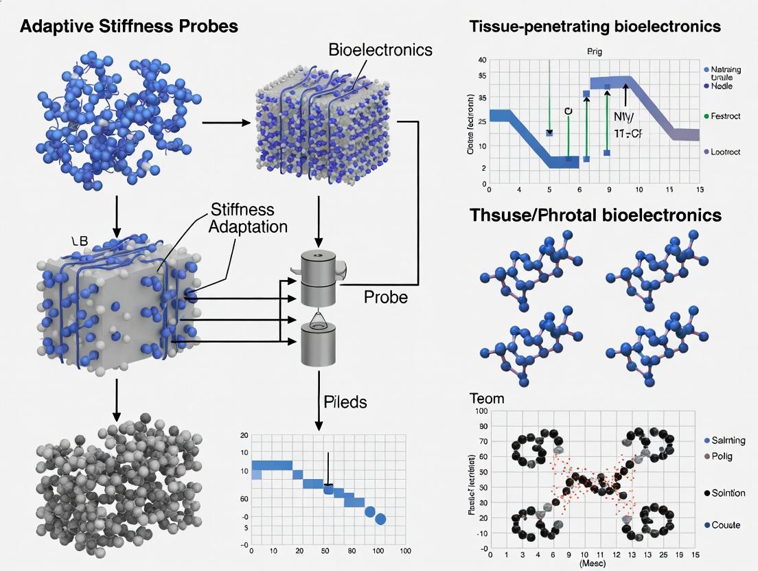
Adaptive Stiffness Probes: The Next Frontier in Tissue-Penetrating Bioelectronics for Neural Recording and Drug Delivery
This article explores the emerging technology of adaptive stiffness probes for bioelectronic interfaces.
Adaptive Stiffness Probes: The Next Frontier in Tissue-Penetrating Bioelectronics for Neural Recording and Drug Delivery
Abstract
This article explores the emerging technology of adaptive stiffness probes for bioelectronic interfaces. Aimed at researchers and drug development professionals, it covers the fundamental principles of materials that transition from rigid for penetration to soft for chronic compatibility. The scope includes material design strategies, fabrication methods, and in vivo applications for neural recording and targeted delivery. We address key challenges in device-tissue mismatch and immune response, and provide a comparative analysis against traditional rigid and fully soft probes, highlighting validation protocols and future research directions for next-generation biomedical implants.
From Rigid to Soft: The Core Principles and Materials Behind Adaptive Stiffness Bioelectronics
The fundamental challenge in chronic neural interfacing lies in the biomechanical mismatch between traditional rigid/semi-rigid probes (e.g., silicon, metal) and soft neural tissue. This mismatch induces chronic inflammatory gliosis, neuronal death, and signal degradation. The following table quantifies the core challenges.
Table 1: Quantitative Impact of Traditional Probe Implantation
| Parameter | Traditional Probe (e.g., Si, Tungsten) | Soft Neural Tissue (Target) | Measured Consequence |
|---|---|---|---|
| Young's Modulus | 102 - 1011 GPa | 0.1 - 15 kPa | 7-9 orders of magnitude mismatch |
| Chronic Glial Scar Thickness | N/A | N/A | 100-500 µm around implant after 6-12 weeks |
| Neuronal Density Loss | N/A | N/A | Up to 50-80% within 100 µm of interface at 12 weeks |
| Single-Unit Yield Decline | N/A | N/A | ~70-90% reduction from Week 1 to Week 12 |
| Signal-to-Noise Ratio (SNR) Decline | N/A | N/A | ~30-50% reduction over 8 weeks |
| Chronic Peak Micro-Motion | N/A | N/A | 5-40 µm relative displacement with breathing/pulse |
Detailed Experimental Protocols
Protocol 2.1: Histological Quantification of Chronic Tissue Damage and Gliosis
Objective: To quantitatively assess neuronal loss and glial scarring around a traditional static implant over a 12-week period.
Materials:
- Male Sprague-Dawley rats (300-350g)
- Traditional silicon Michigan-style probe (2 mm shank, 100 µm thick)
- Stereotaxic frame + surgical tools
- Perfusion pump, 4% Paraformaldehyde (PFA)
- Primary Antibodies: Mouse anti-NeuN (neurons), Rabbit anti-Iba1 (microglia), Chicken anti-GFAP (astrocytes)
- Fluorescent secondary antibodies, DAPI, mounting medium
- Confocal or multiphoton microscope
Procedure:
- Implantation: Anesthetize rat and secure in stereotaxic frame. Perform craniotomy over primary motor cortex (M1; AP: +1.5 mm, ML: +2.0 mm from bregma). Slowly insert the silicon probe to a depth of 1.5 mm at 1 µm/s. Secure probe to skull with dental acrylic.
- Recovery & Time Points: Allow animals to recover. Establish cohorts for perfusion at 1, 4, and 12 weeks post-implantation (n=5 per group).
- Perfusion & Sectioning: Transcardially perfuse with PBS followed by 4% PFA. Extract brain, post-fix for 24h, and section coronally (50 µm) through the implant tract using a vibratome.
- Immunohistochemistry: Perform free-floating IHC. Block sections in 5% normal goat serum. Incubate in primary antibody cocktail (NeuN, Iba1, GFAP) for 48h at 4°C. Wash and incubate with appropriate secondaries + DAPI for 2h.
- Imaging & Analysis: Image using a 20x objective. For each section, capture z-stacks spanning the implant tract.
- Neuronal Density: Count NeuN+ nuclei in concentric bins (0-50, 50-100, 100-200 µm) from the probe tract edge. Normalize to contralateral hemisphere counts.
- Gliosis Index: Measure fluorescence intensity of Iba1 and GFAP in the same concentric bins. Calculate intensity ratio (ipsilateral/contralateral).
- Scar Thickness: Define the glial scar boundary as the radial distance where GFAP/Iba1 intensity falls to 50% of its maximum. Average measurements from 8 radial directions.
Protocol 2.2: Electrophysiological Recording of Chronic Signal Degradation
Objective: To longitudinally track the quality and yield of single-unit recordings from a traditional implanted probe.
Materials:
- Rat with chronically implanted 16-channel silicon probe (as in Protocol 2.1).
- Headstage, commutator, and neural data acquisition system (e.g., Intan, Open Ephys).
- Spike sorting software (e.g., Kilosort, MountainSort).
- Behavioral monitoring chamber.
Procedure:
- Chronic Recording Setup: Connect the implanted probe to a headstage and commutator to allow free movement. Record from all channels daily for the first week, then 3x per week until week 12.
- Data Acquisition: During each 30-minute recording session, record neural data while the animal rests quietly. Sample at 30 kHz with a high-pass filter at 300 Hz. Synchronize with video for behavioral state annotation (quiet wakefulness).
- Spike Sorting & Metrics: For each session, process data through a standardized spike sorting pipeline.
- Single-Unit Yield: Count the number of well-isolated single units (SNR > 2.5, presence of a clear refractory period in autocorrelogram) per session.
- Signal Amplitude: For each tracked unit, measure the peak-to-trough amplitude of the mean waveform.
- Population Stability: Calculate the percentage of units from Week 1 that can be reliably tracked (based on waveform and firing characteristics) through subsequent weeks.
- Correlation with Histology: At terminal time point (12 weeks), perform perfusion and histology as in Protocol 2.1. Correlate final electrophysiology metrics with histological outcomes from the same animal.
Visualizing Key Mechanisms and Workflows
Title: Tissue Damage & Signal Loss Pathway from Rigid Implants
Title: Experimental Workflow for Assessing Chronic Failure
The Scientist's Toolkit: Research Reagent Solutions
Table 2: Essential Materials for Investigating Implant-Tissue Interface Failure
| Item | Function & Rationale |
|---|---|
| High-Modulus Probes (Silicon Michigan Arrays, Tungsten Microwires) | Serve as the experimental "challenge" control. Their well-documented rigidity (GPa range) is essential for establishing the baseline of tissue damage and signal degradation. |
| Antibody Cocktail: NeuN, Iba1, GFAP | Gold-standard markers for quantifying the key histological outcomes: neuronal survival (NeuN), microglial activation (Iba1), and astrocytic scarring (GFAP). Multiplexing allows spatial correlation. |
| Slowly Degrading Skull Adhesive (e.g., Charisma, Paladur dental acrylic) | Critical for stable, long-term fixation of the traditional probe to the skull. Instability at the skull mount confounds interpretation of intracortical micromotion effects. |
| Chronic Commutator System | Enables longitudinal neural recording in freely behaving animals without cable twisting, which is essential for assessing natural behavioral state effects on signal quality over time. |
| Standardized Spike Sorting Suite (e.g., Kilosort2/3) | Provides objective, reproducible metrics for single-unit isolation, yield, and waveform characteristics, allowing quantitative tracking of signal degradation across labs. |
| Vibratome for Free-Floating Sectioning | Produces high-quality, intact tissue sections containing the fragile implant tract, which is crucial for accurate radial analysis of gliosis and neuronal loss. |
| Fluorescent Microsphere-Labeled Probes | Probes coated with traceable fluorescent beads allow precise post-extraction localization of the implant track in tissue for perfect alignment of histological metrics with the recording site. |
Within the thesis framework of developing adaptive stiffness probes for tissue-penetrating bioelectronics, biomimicry provides the foundational design principles. Natural systems, such as parasites, insect stingers, and plant roots, have evolved specialized mechanisms to penetrate, anchor within, and dynamically interface with soft biological tissues while minimizing damage and immune response. This document outlines application notes and protocols for studying these natural interfaces to inform the design of next-generation bioelectronic probes that transition from rigid (for insertion) to soft (for chronic integration).
Table 1: Characteristics of Natural Tissue-Penetrating Systems
| Natural System | Penetration Mechanism | Anchoring/Interface Strategy | Stiffness Modulus (Approx.) | Key Bio-Inspired Feature |
|---|---|---|---|---|
| Mosquito Proboscis | Dynamic microneedling, serrated cuticle | Anti-adhesive coating, fluidic uptake | Labium: ~10 GPa; Fascicle: ~70 GPa (Cuticle) | Micron-scale serrations, pain minimization via dynamic motion. |
| Porcupine Quill | Asymmetric, backward-facing barbs | Mechanical interlocking via barbs | Cortex: ~0.4 GPa; Medulla: ~0.05 GPa | Barb geometry drastically reduces penetration force (~60%) and enhances adhesion. |
| Parasitic Worm (e.g., Schistosoma) | Enzymatic secretion (proteases) | Molecular mimicry, surface glycocalyx | Body tissue: ~1-10 kPa | Dynamic biochemical softening of host tissue for entry. |
| Plant Root Hairs | Turgor pressure, cell wall softening | Increased surface area, chemical signaling | Cell Wall: ~100-500 MPa | Directional growth via chemotaxis, gentle mechanical pushing. |
Table 2: Measured Force & Performance Metrics
| Model | Penetration Force Reduction vs. Control | Key Measured Parameter | Value | Implication for Probe Design |
|---|---|---|---|---|
| Barbed Quill (vs. Needle) | ~54-76% | Pull-out Force Increase | +280% (in skin simulant) | Barbs enable secure anchoring with minimal insertion damage. |
| Mosquito Fascicle | N/A | Peak Insertion Force (Rat Skin) | ~16.5 µN | Ultra-low force prevents nociceptor activation (pain). |
| Adaptive Stiffness Polymer (Hydrogel) | N/A | Stiffness Transition Range (Hydration) | 100 MPa -> 10 kPa | Mimics root/parasite transition from rigid penetrator to soft interface. |
Experimental Protocols
Protocol 3.1: Micromechanical Testing of Biomimetic Probe Insertion
Objective: Quantify the penetration force and tissue damage of bio-inspired probe geometries in synthetic and ex vivo tissues. Materials: Biomimetic probe prototypes (e.g., 3D-printed with barbed geometries), force transducer (µN-mN range), synthetic hydrogel tissue phantom (e.g., ~10% gelatin or PDMS with tuned elastic modulus), ex vivo tissue sample (e.g., rat skin, liver), high-speed camera, PBS. Procedure:
- Tissue Phantom Preparation: Prepare 10% (w/v) gelatin in PBS. Pour into a custom mold and refrigerate at 4°C for 2 hrs to set. Characterize storage modulus (G') via rheometry (Target: ~10-20 kPa).
- Probe Mounting: Secure the biomimetic probe to the platform of a calibrated micromechanical tester or a force transducer mounted on a micromanipulator.
- Insertion Test:
- Position the tissue phantom or ex vivo sample firmly on the stage.
- Align the probe perpendicular to the tissue surface.
- Program the manipulator for a constant insertion velocity (e.g., 1 mm/s).
- Initiate insertion to a depth of 5 mm while simultaneously recording force (at 1 kHz) and visualizing with high-speed camera (1000 fps).
- Pause for 5 seconds at full depth.
- Retract the probe at the same velocity.
- Data Analysis:
- Plot force vs. displacement.
- Identify peak insertion force (Finsert), steady-state force (Fsteady), and peak pull-out force (F_pullout).
- Calculate work of insertion (Win) and work of extraction (Wout) from the area under the curve.
- Correlate force spikes with visual damage events from video.
Protocol 3.2: Assessing Bio-Fouling & Immune Response on Bio-Inspired Coatings
Objective: Evaluate the anti-fouling performance of coatings mimicking mosquito cuticle or parasitic surface chemistry. Materials: Coated probe substrates, primary macrophages (e.g., RAW 264.7 cell line), cell culture media, fluorescent albumin (or other protein solution), fluorescent dye for viability (e.g., Calcein-AM/EthD-1), confocal microscope, flow cytometer. Procedure:
- Protein Adsorption Assay:
- Incubate coated and uncoated (control) substrates in 1 mg/mL fluorescently tagged albumin solution for 1 hr at 37°C.
- Rinse gently 3x with PBS to remove non-adsorbed protein.
- Image surfaces using confocal microscopy with identical laser power and gain settings.
- Quantify adsorbed protein fluorescence intensity per unit area using image analysis software (e.g., ImageJ).
- Macrophage Adhesion & Activation Assay:
- Seed macrophages onto coated substrates at 50,000 cells/cm² in complete media. Incubate for 24 hrs.
- Carefully rinse with PBS to remove non-adherent cells.
- Stain live/dead cells and image at least 5 random fields per substrate.
- Count adherent cells and calculate cell density.
- For activation, collect supernatant and measure pro-inflammatory cytokine (e.g., TNF-α, IL-6) levels via ELISA.
- Alternatively, trypsinize adherent cells and analyze surface activation markers (e.g., CD86) via flow cytometry.
Signaling Pathways in Tissue Response to Penetration
Title: Immune & Pain Signaling Post-Tissue Penetration
Biomimetic Probe Development Workflow
Title: Biomimetic Probe Development Iterative Cycle
The Scientist's Toolkit: Research Reagent Solutions
Table 3: Essential Materials for Biomimetic Interface Research
| Item / Reagent | Function / Application | Example Product/Specification |
|---|---|---|
| Poly(N-isopropylacrylamide) (PNIPAM) | Thermo-responsive hydrogel for adaptive stiffness. Stiff at room temp (insertion), soft at 37°C (integration). | Sigma-Aldrich, 99% linear PNIPAM, Mw ~40,000. |
| PEG-DMA (Polyethylene glycol dimethacrylate) | Hydrogel crosslinker for tuning mechanical properties of synthetic tissue phantoms and probe coatings. | Thermo Fisher Scientific, PEG-DMA, Mn 1000. |
| Fluorescent Albumin (e.g., FITC-BSA) | Protein adsorption tracer for quantifying biofouling on probe surfaces. | Invitrogen, Albumin from bovine serum, FITC conjugate. |
| Matrigel or Collagen I Matrix | 3D Tissue Mimetic for advanced cell culture and insertion testing in a biomimetic extracellular matrix. | Corning, Matrigel Basement Membrane Matrix, Growth Factor Reduced. |
| RAW 264.7 Cell Line | Murine macrophage model for standardized in vitro assessment of foreign body immune response. | ATCC, RAW 264.7 (TIB-71). |
| Mouse TNF-α ELISA Kit | Quantitative cytokine analysis for measuring macrophage activation levels in response to materials. | R&D Systems, Mouse TNF-α Quantikine ELISA Kit. |
| Photolithography Resists (e.g., SU-8) | Microfabrication of high-aspect-ratio, bio-inspired probe geometries (e.g., microneedles, barbs). | Kayaku Advanced Materials, SU-8 2000 series. |
| Sylgard 184 PDMS | Elastomeric tissue phantom and flexible substrate for soft electronic integration. | Dow Silicones, 10:1 base to curing agent ratio. |
Within the field of tissue-penetrating bioelectronics, a key challenge is the implantation of devices that are stiff enough for precise insertion but soft enough to minimize chronic immune response and tissue damage. Adaptive stiffness probes, which can switch their mechanical properties in situ, offer a revolutionary solution. This Application Note details the primary external triggers—thermal, solvent, hydration, and magnetic—used to induce such stiffness switching, providing protocols for their implementation and evaluation in a research setting.
Thermal Trigger Mechanisms
Thermal responsiveness is commonly achieved through polymers with a Lower Critical Solution Temperature (LCST) or phase-change materials (PCMs). Poly(N-isopropylacrylamide) (pNIPAM) is a canonical example, undergoing a reversible coil-to-globule transition and expelling water above its LCST (~32°C), significantly increasing modulus.
Quantitative Data: Thermal-Responsive Materials
| Material/System | Transition Temp. (°C) | Stiffness Change (Modulus) | Switching Time | Ref. (Example) |
|---|---|---|---|---|
| pNIPAM hydrogel | ~32 | 10 kPa (swollen) -> 1 MPa (collapsed) | Seconds - Minutes | Adv. Mater. 2023 |
| PEG-PCL-PEG triblock | 37-45 (Tm of PCL) | 5 MPa (solid) -> 50 kPa (melt) | <60 s | Biomacromolecules 2024 |
| Shape Memory Polymer (PCL-based) | 40 (Tg) | 2 GPa (glassy) -> 10 MPa (rubbery) | <30 s | Sci. Robot. 2023 |
Protocol 1.1: Characterizing Thermally-Activated Stiffness Switching in Hydrogels Objective: To measure the reversible change in compressive modulus of a pNIPAM-co-AAc hydrogel across its LCST. Materials:
- Synthesized pNIPAM-co-Acrylic Acid hydrogel disc (8mm diameter, 2mm height).
- Phosphate Buffered Saline (PBS), pH 7.4.
- Rheometer with Peltier temperature control plate (or DMA with fluid bath).
- Temperature-controlled water bath(s). Procedure:
- Hydrate the hydrogel sample in PBS at 25°C for 24h.
- Mount the sample on the rheometer parallel plate. Apply a thin layer of silicone oil to the exposed edges to prevent drying.
- Set a temperature sweep protocol: 25°C -> 45°C -> 25°C at a rate of 1°C/min.
- Apply a constant oscillatory strain (1%, within LVR) at 1 Hz frequency.
- Record the storage modulus (G') as a function of temperature. The sharp increase in G' indicates the LCST transition.
- The hysteresis and reversibility can be assessed from the heating/cooling cycles. Data Analysis: Plot G' vs. T. The transition temperature can be identified as the inflection point. Calculate the stiffness switching ratio (G' at 45°C / G' at 25°C).
Diagram Title: Thermal Stiffness Switching Mechanism
Solvent & Hydration Trigger Mechanisms
These triggers exploit the plasticizing effect of solvents or water. A dry, glassy polymer can be stiff for insertion but softens upon absorbing physiological fluid (hydration). Conversely, solvent-responsive systems (e.g., solvent-swollen elastomers) can stiffen dramatically upon solvent loss via evaporation or osmosis.
Quantitative Data: Solvent/Hydration-Responsive Systems
| System | Trigger | Stiffness Change (Modulus) | Switching Time | Key Mechanism |
|---|---|---|---|---|
| PVAc-based SMP | Hydration (PBS) | 1.8 GPa (dry) -> 25 MPa (wet) | 10-15 mins | Water Plasticization (Tg reduction) |
| PVA hydrogel | Dehydration (Air) | 100 kPa (hydrated) -> 80 MPa (dry) | Hours | Loss of Plasticizing Water |
| DMSO-swollen PDMS | DMSO Exchange (to Water) | 50 kPa (swollen) -> 2 MPa (deswollen) | Minutes | Osmotic Stress & Chain Collapse |
Protocol 2.1: Measuring Hydration-Induced Softening for Insertion Guides Objective: To quantify the time-dependent reduction in flexural modulus of a shape-memory polymer filament upon immersion in simulated physiological fluid. Materials:
- Poly(vinyl acetate) (PVAc) based SMP filament (dia. 200 µm).
- PBS, pH 7.4, at 37°C.
- Dynamic Mechanical Analyzer (DMA) with submersion clamp or a custom 3-point bend fixture in a fluid cell.
- Micro-scale force transducer. Procedure:
- Clamp the dry SMP filament in a 3-point bending configuration with a fixed span.
- Perform an initial bend test on the dry filament to establish baseline modulus (E_dry).
- Immerse the entire fixture and sample in pre-warmed PBS (37°C). Start timer.
- At predetermined timepoints (e.g., 1, 2, 5, 10, 15 min), perform a rapid bend test (small strain to avoid affecting hydration).
- Record force-displacement data at each timepoint.
- Continue until modulus plateaus (fully hydrated). Data Analysis: Calculate modulus E(t) at each timepoint. Plot normalized modulus (E(t)/E_dry) vs. time. Fit with a Fickian diffusion model to predict softening kinetics for different probe diameters.
Magnetic Trigger Mechanisms
Magnetic fields can remotely and rapidly induce stiffness changes in composites containing ferromagnetic or superparamagnetic particles (e.g., Fe₃O₄). Mechanisms include magneto-thermal heating (inducing a thermal transition) and direct magneto-rheological effects where field alignment of particles creates a reinforcing network.
Quantitative Data: Magneto-Responsive Composites
| Composite | Particle (Vol%) | Trigger (Field) | Stiffness Change | Response Time | Primary Mechanism |
|---|---|---|---|---|---|
| pNIPAM/Fe₃O₄ | 5% (20 nm) | Alternating Magnetic Field (AMF, 300 kHz) | ΔG' = +150 kPa | < 30 s | Magneto-Thermal (LCST) |
| PDMS/CIP | 30% (Carbonyl Iron Powder) | Static Field (500 mT) | 0.5 MPa -> 3.5 MPa | < 1 s | Magneto-Rheological |
| PEG-diacrylate/CoFe₂O₄ | 10% | Static Field (300 mT) | Storage Modulus 2x increase | Instantaneous | Particle Chain Jamming |
Protocol 3.1: Remote Stiffening via Magneto-Thermal Trigger Objective: To demonstrate remote activation of a shape-memory polymer nanocomposite using an alternating magnetic field (AMF). Materials:
- PCL-based SMP doped with 8 wt% superparamagnetic Fe₃O₄ nanoparticles.
- AMF generator with solenoid coil (frequency: 300-400 kHz, adjustable field strength).
- Infrared thermal camera.
- Dynamical Mechanical Analysis (DMA) or nanoindenter positioned within the coil. Procedure:
- Fabricate test samples (e.g., rectangular beams) of the magnetic nanocomposite.
- Mount sample in the DMA within the AMF coil center. Ensure no metallic interference with DMA mechanics.
- Pre-set DMA to a low oscillatory force/stress to monitor modulus.
- Apply AMF at a predetermined field strength (e.g., 20 kA/m). Simultaneously monitor surface temperature via IR camera.
- Apply AMF until sample temperature exceeds the Tm of PCL (~60°C) and modulus drops (softening for shape change). For stiffening upon cooling:
- While maintaining AMF to hold temperature, deform the sample. Then, turn off AMF and allow rapid cooling/solidification, locking the deformed, stiff state.
- Re-apply AMF to revert to the original soft shape. Data Analysis: Correlate real-time modulus (from DMA) with sample temperature (from IR). Calculate switching speed and cyclic stability.
Diagram Title: Magnetic Stiffness Switching Pathways
The Scientist's Toolkit: Research Reagent Solutions
| Item | Function/Description | Example Supplier(s) |
|---|---|---|
| pNIPAM (N-isopropylacrylamide) | Thermo-responsive monomer for synthesizing LCST hydrogels. | Sigma-Aldrich, TCI Chemicals |
| PCL (Polycaprolactone), Mn 50-80k | Biodegradable polyester with low Tm (~60°C) for thermal/SMPs. | Sigma-Aldrich, Lactel Absorbables |
| Fe₃O₄ Nanoparticles (10-20 nm, oleic acid coated) | Superparamagnetic particles for magneto-thermal composites. | Sigma-Aldrich, Nanocs |
| Carbonyl Iron Powder (CIP), 3-5 µm | Soft magnetic particles for magneto-rheological elastomers. | BASF, Sigma-Aldrich |
| Photo-initiator (Irgacure 2959) | UV initiator for crosslinking PEG-diacrylate and other hydrogels. | BASF, Sigma-Aldrich |
| PBS, pH 7.4 (1X), sterile | Standard hydration/swelling medium for physiological simulation. | Thermo Fisher, Gibco |
| DMEM/F-12 cell culture medium | For advanced hydration studies with ionic & nutrient complexity. | Thermo Fisher, Sigma-Aldrich |
| Rheometer with Peltier & Hood | Essential for temperature- and solvent-controlled modulus measurements. | TA Instruments, Anton Paar |
| DMA with Humidity/Solvent Cup | For precise thermomechanical analysis under hydration. | TA Instruments, Mettler Toledo |
| Alternating Magnetic Field (AMF) System | Custom or commercial system for remote magneto-thermal heating. | Ambrell, Nanoscale Biomagnetics |
Application Notes
These advanced material classes are critical for the development of next-generation adaptive stiffness probes in bioelectronics. Their unique stimuli-responsive properties enable minimally invasive insertion and subsequent conformal integration with neural or soft tissue, which is essential for stable, long-term electrophysiological recording, stimulation, and drug delivery.
Shape Memory Polymers (SMPs): Primarily used for their "soften-on-demand" capability. A stiff, glassy probe can be inserted through protective sheaths or tissue with minimal trauma, then triggered (via heat, light, or solvent) to soften and match the modulus of surrounding brain tissue (~1-10 kPa), reducing chronic immune response and improving signal fidelity.
Hydrogels: Offer inherent biocompatibility and tissue-like mechanical properties. Their high water content facilitates nutrient/waste diffusion. Crosslinking density can be tuned for stiffness switching via chemical, thermal, or optical triggers. Ideal for drug-eluting coatings or as the primary matrix for soft electrodes.
Liquid Crystal Elastomers (LCEs): Provide programmable, anisotropic shape change and actuation. When aligned, they can undergo large, reversible contractions or bends upon thermal or photothermal actuation. This is exploited for probe deployment, micro-positioning of electrodes post-insertion, or applying gentle mechanical stimulation to cells.
Composites: Integrate the above matrices with functional fillers (conductive polymers, graphene, metallic nanowires, magnetic particles) to create multifunctional probes. The composite approach decouples electrical/mechanical properties, allowing for soft, conductive traces within a stiffening SMP backbone for insertion.
Table 1: Comparative Properties of Key Adaptive Material Classes
| Material Class | Typical Modulus Range (Temporary/Insertion) | Typical Modulus Range (Activated/Operational) | Primary Stimulus | Characteristic Response Time | Key Advantage for Bioelectronics |
|---|---|---|---|---|---|
| Shape Memory Polymers | 0.1 - 2 GPa | 0.1 - 10 MPa | Thermal, Solvent, Light | Seconds to Minutes | Large, one-time stiffness reduction (>1000x) |
| Hydrogels | 1 - 100 kPa (tunable) | 0.1 - 50 kPa (tunable) | Thermal, Ionic, pH, Light | Seconds to Hours | Native tissue mimicry, high biocompatibility |
| Liquid Crystal Elastomers | 0.1 - 1 MPa | 0.1 - 1 MPa (with ~40% strain) | Thermal, Light | Milliseconds to Seconds | Programmable, reversible macro-shape change |
| Conductive Composites | 1 MPa - 1 GPa | 1 kPa - 100 MPa | Dependent on matrix | Dependent on matrix | Multifunctionality (conductive, magnetic, stiffening) |
Table 2: Performance Metrics in Recent Tissue-Penetrating Probe Studies
| Material System | Insertion Force Reduction | Chronic Glial Scarring (vs. Traditional Silicon) | Stable Recording Duration | Reference (Example) |
|---|---|---|---|---|
| PCL-based SMP Probe | ~70% | ~60% reduction at 8 weeks | > 4 weeks | (Zhang et al., 2022) |
| PEDOT:PSS Hydrogel Coated Si Probe | ~40% (friction) | ~50% reduction at 6 weeks | > 8 weeks | (Qiang et al., 2023) |
| Magnetic LCE Microgripper | N/A (untethered) | Not quantified | N/A (actuator) | (Kim et al., 2021) |
| CNT-SMP Composite Fiber | ~65% | ~55% reduction at 12 weeks | > 12 weeks | (Park et al., 2023) |
Experimental Protocols
Protocol 1: Fabrication and Thermo-Mechanical Cycling of a Heat-Triggered SMP Neural Probe
Objective: To fabricate a microfabricated SMP probe and characterize its stiffness switching for cortical insertion.
Materials: See "The Scientist's Toolkit" below.
Procedure:
- Mold Fabrication: Use standard photolithography and deep reactive ion etching (DRIE) on a silicon wafer to create a high-aspect-ratio negative mold of the probe geometry (shank length: 5 mm, width: 150 µm, thickness: 50 µm).
- Polymer Preparation: Dissolve poly(ε-caprolactone) (PCL, Mn 50,000) in anhydrous chloroform (30% w/v) at 50°C overnight.
- Solution Casting & Programming: Pour the PCL solution into the silicon mold. Place in a vacuum desiccator to remove bubbles, then evaporate solvent at room temp for 24h. Demold the flexible film.
- Program the Temporary Shape: Heat the PCL film on a hotplate at 70°C (above Tm) for 5 min. While hot, stretch it uniaxially by 200% and clamp it in a custom fixture. Cool to 4°C to fix the temporary, elongated shape.
- Thermo-Mechanical Testing (DMA): a. Mount the programmed probe sample in a dynamic mechanical analyzer (DMA) in tension mode. b. Apply a pre-load force of 0.01 N. c. Run a temperature ramp from 25°C to 70°C at 3°C/min, applying a small oscillatory strain (0.1%, 1 Hz). d. Record the storage modulus (E') throughout. The sharp drop at ~55-60°C indicates the glass transition/stiffness switch.
- Ex Vivo Insertion Test: a. Mount the programmed, stiff probe on a micromanipulator. b. Position over a slab of 0.6% agarose brain tissue phantom. c. Advance the probe at 1 mm/s to a depth of 3 mm while measuring force with a load cell. d. Retract the probe, activate it by local heating to 60°C for 60s, and repeat the insertion. Compare peak insertion forces.
Protocol 2: Photopatterning a Conductive Hydrogel Coating on a Microelectrode Array
Objective: To create spatially defined, soft conductive hydrogel contacts on a rigid Michigan-style electrode array.
Materials: See "The Scientist's Toolkit" below.
Procedure:
- Substrate Preparation: Clean a standard silicon microelectrode array (MEA) with piranha solution (Caution!), rinse with DI water, and treat with oxygen plasma for 2 min to ensure hydrophilicity.
- Hydrogel Precursor Formulation: Prepare solution under red light. Mix: 20% w/v GelMA (methacrylated gelatin), 1% w/v LAP photoinitiator, 3% w/v PEDOT:PSS dispersion, and 0.1% w/v MBAA crosslinker in DI water. Vortex thoroughly and centrifuge to degas.
- Coating & Patterning: Pipette a small volume of precursor onto the electrode sites. Carefully place a transparency photomask (with clear features only over electrode contacts) in contact with the substrate. Expose to 405 nm UV light (10 mW/cm²) for 30 seconds.
- Development: Immerse the entire chip in warm (37°C) DI water for 5 minutes. The unexposed, non-crosslinked precursor will dissolve, leaving hydrogel microdots only on the exposed electrode contacts.
- Characterization: a. Impedance: Measure electrochemical impedance spectroscopy (EIS) from 1 Hz to 100 kHz in PBS at 37°C. Compare bare gold vs. hydrogel-coated electrode impedance at 1 kHz. b. Cytocompatibility: Seed NIH/3T3 fibroblasts around the coated array. Culture for 72h, then perform a live/dead assay (calcein AM/ethidium homodimer-1). Viability should be >90%.
Protocol 3: Actuation Characterization of a Photothermal LCE Micro-Actuator
Objective: To measure the light-induced contraction of an LCE film doped with near-infrared absorber for potential use in probe positioning.
Materials: See "The Scientist's Toolkit" below.
Procedure:
- LCE Synthesis & Alignment: a. Synthesize a main-chain LCE via a two-step thiol-acrylate Michael addition and photopolymerization reaction, using RM257 mesogen and a dithiol chain extender. b. Dope the precursor mixture with 0.1% w/w IR-806 NIR dye. c. Cast mixture between two glass slides coated with rubbed polyimide to induce planar molecular alignment. Expose to 365 nm UV light (50 mW/cm²) for 10 min to cure.
- Sample Preparation: Demold and cut the aligned LCE film into a cantilever strip (10 mm x 1 mm).
- Photothermal Actuation Test: a. Clamp one end of the strip vertically. a. Illuminate the sample with an 808 nm diode laser at a controlled power density (e.g., 0.5 W/cm²). Use a thermal camera to monitor surface temperature. b. Record the displacement of the free end at 60 fps using a high-speed camera. c. Use digital image correlation (DIC) software to analyze the strain in the film as a function of time and localized temperature.
- Cycling Test: Subject the actuator to 100 on/off cycles (10s illumination, 30s rest). Plot strain versus cycle number to assess fatigue and reproducibility.
Diagrams
SMP Probe Stiffness-Switching Workflow
Logic of Adaptive Materials for Neural Interfaces
The Scientist's Toolkit
Table 3: Essential Research Reagents & Materials
| Item | Function in Adaptive Probe Research | Example Supplier/Catalog |
|---|---|---|
| Poly(ε-caprolactone) (PCL), Mn 45,000-80,000 | A biodegradable, thermoplastic SMP with a tunable Tm (~55°C). Workhorse material for stiffness-switching probes. | Sigma-Aldrich, 440744 |
| Gelatin Methacryloyl (GelMA) | A photopolymerizable, biologically derived hydrogel prepolymer. Forms soft, cell-adhesive matrices for coatings. | Advanced BioMatrix, GMA-3 or synthesized in-house. |
| RM257 Liquid Crystal Monomer | A widely used diacrylate mesogen for synthesizing LCEs with nematic alignment. | Wilshire Technologies, WR-301 or equivalent. |
| PEDOT:PSS Dispersion (Clevios PH1000) | Conducting polymer for creating transparent, conductive hydrogel or composite electrodes. | Heraeus, Clevios PH 1000. |
| 2-Hydroxy-4′-(2-hydroxyethoxy)-2-methylpropiophenone (Irgacure 2959) | A cytocompatible UV photoinitiator for crosslinking hydrogels. | Sigma-Aldrich, 410896. |
| Lithium phenyl-2,4,6-trimethylbenzoylphosphinate (LAP) | A highly efficient water-soluble blue light photoinitiator for hydrogel patterning. | TCI Chemicals, L0277. |
| IR-806 Near-Infrared Dye | Photothermal agent for doping into LCEs or SMPs to enable light-triggered activation. | Sigma-Aldrich, 595238. |
| Polydimethylsiloxane (PDMS) Sylgard 184 | For creating soft molding fixtures, tissue phantoms, and encapsulation. | Dow, SYLGARD 184. |
| SU-8 Photoresist Series (2000, 3000) | Negative photoresist for high-aspect-ratio microfabrication of probe molds. | Kayaku Advanced Materials. |
| Agarose, Low Gelling Temperature | For preparing standardized brain tissue-mimicking phantoms for insertion testing. | Sigma-Aldrich, A5030. |
1. Application Notes
The integration of bioelectronic probes into neural and other soft tissues presents a fundamental mechanical challenge. The dynamic mismatch between probe stiffness and the viscoelastic, non-linear tissue environment generates interfacial stress and strain, driving acute injury and chronic foreign body response (FBR). This document outlines the theoretical frameworks for modeling these mechanical interactions, with direct application to the design and evaluation of adaptive stiffness probes. These probes leverage stimuli-responsive materials to be rigid for precise insertion and subsequently soften in situ to match tissue modulus, minimizing mechanical mismatch.
- Acute Insertion Phase Modeling: The primary goal is to minimize insertion force and immediate tissue damage (strain > 20-30%). Models treat tissue as a hyperelastic or poroelastic medium (e.g., Ogden, Neo-Hookean models) penetrated by a rigid indenter (probe). Key output parameters are insertion force, principal stress concentrations at the probe tip and shaft, and the extent of the strained tissue volume.
- Chronic Implantation Phase Modeling: The focus shifts to the sustained mechanical interaction driving the FBR. Models analyze time-dependent strain energy density at the probe-tissue interface, which correlates with glial scarring and neurodegeneration. Critical factors include probe geometry, chronic pressure, and micromotion-induced cyclic strain. Adaptive stiffness probes aim to reduce chronic interfacial strain energy by 1-2 orders of magnitude compared to traditional silicon or metal probes.
2. Core Theoretical Data & Parameters
Table 1: Key Material Properties for Modeling
| Parameter | Typical Neural Tissue (Brain) | Traditional Probe (Silicon) | Adaptive Stiffness Probe (Hydrated) | Modeling Relevance |
|---|---|---|---|---|
| Elastic Modulus (E) | 1 - 3 kPa | 130 - 180 GPa | 10 - 500 kPa | Dictates static mismatch; stress (σ) = E * ε. |
| Pseudo-Stiffness (Insertion) | N/A | ~1-10 N/m | 0.1 - 5 N/m | Predicts buckling resistance during insertion. |
| Poisson's Ratio (ν) | ~0.49 (nearly incompressible) | 0.22 - 0.28 | 0.3 - 0.49 | Affects deformation field and pressure distribution. |
| Stress Relaxation Time Constant | 1 - 100 seconds | Negligible | Tunable (seconds to minutes) | Critical for modeling time-dependent force reduction post-insertion. |
Table 2: Model-Predicted vs. Measured Outcomes
| Analysis Phase | Model Type | Key Output Variable | Target/Desired Value (Adaptive Probe) | Correlated Biological Outcome |
|---|---|---|---|---|
| Insertion | Quasi-Static, Hyperelastic | Max Insertion Force (F_max) | < 1 mN for μ-scale probes | Reduced acute hemorrhage & primary cell death. |
| Insertion | Dynamic, Fracture-based | Tissue Strain (ε) at 50 μm radius | < 20% | Preserved extracellular matrix integrity. |
| Chronic | Linear Viscoelastic | Interfacial Pressure (P) | < 50 Pa | Reduced sustained compression ischemia. |
| Chronic | Cyclic, Fatigue | Strain Energy Density (U) at interface | < 0.1 J/m³ | Attenuated glial activation & scarring thickness. |
3. Experimental Protocols
Protocol 3.1: Ex Vivo Insertion Force & Strain Field Validation
- Objective: Quantify insertion mechanics and validate hyperelastic finite element model (FEM) predictions.
- Materials: Adaptive stiffness probe, precision micro-actuator, force sensor (μN resolution), transparent tissue phantom or acute brain slice, fluorescence microscope, particle image velocimetry (PIV) beads.
- Method:
- Embed fluorescent microbeads (1 μm) in a 0.5% agarose/basement membrane matrix phantom (E ≈ 3 kPa).
- Mount phantom under microscope. Mount probe on actuator with in-line force sensor.
- Insertion: Drive probe into phantom at 1 mm/s. Record force at 1 kHz. Acquire high-speed video (100 fps) of bead field.
- PIV Analysis: Use PIV software to compute displacement vectors between frames. Calculate Lagrangian strain tensor fields.
- Model Correlation: Input probe geometry and material properties into FEM software (e.g., COMSOL). Simulate insertion. Correlate simulated force-displacement curve and spatial strain maps with experimental data. Optimize model parameters.
Protocol 3.2: Chronic Micromotion-Induced Strain Analysis
- Objective: Measure chronic interfacial strain and correlate with FBR in a rodent model.
- Materials: Adaptive stiffness probe, traditional rigid control probe, stereotaxic frame, awake behaving rodent setup, in vivo microdialysis pump, histological equipment.
- Method:
- Implant probes (n≥5 per group) into target brain region. Allow stiffness transition (e.g., hydrogel swelling, polymer softening).
- Micromotion Application: For 28 days, use a calibrated piezoelectric actuator to impose controlled, periodic probe displacement (10 μm amplitude, 1 Hz) for 1 hour daily to simulate physiological micromotion.
- Tethering Force Measurement: Use a miniature load cell in series with the probe tether to record chronic interfacial force weekly.
- Perfusion & Histology: At endpoint, perfuse-fix animals. Section brain. Immunostain for GFAP (astrocytes), Iba1 (microglia), and NeuN (neurons).
- Quantification: Measure scarring thickness (μm) and neuronal density within 150 μm of probe track. Correlate with measured forces and FEM-predicted cyclic strain energy density.
4. Visualization Diagrams
Theoretical Modeling Workflow for Adaptive Probes
Chronic FBR Pathway Driven by Mechanical Strain
5. The Scientist's Toolkit: Research Reagent Solutions
Table 3: Essential Materials for Experimental Validation
| Item | Function & Rationale |
|---|---|
| Polyethylene Glycol (PEG)-Based Hydrogels | Tunable matrix for tissue phantoms; modulus can be matched to brain via crosslink density. Used for ex vivo mechanical testing. |
| Stimuli-Responsive Polymers (e.g., PEDOT:PSS, PLGA) | Core materials for adaptive probes. Stiffness changes via solvent (water) absorption, temperature, or enzymatic action. |
| Fluorescent Polyethylene Microspheres (0.5-2 μm) | Used as tracer particles in transparent phantoms for Particle Image Velocimetry (PIV) to quantify strain fields during insertion. |
| Primary Antibodies (GFAP, Iba1, NeuN) | For immunohistochemical quantification of glial scarring (GFAP, Iba1) and neuronal health (NeuN) around chronic implants. |
| Silicon-on-Insulator (SOI) Wafers | Standard substrate for fabricating traditional rigid control probes with precise geometries (e.g., Michigan or Utah style arrays). |
| Finite Element Analysis Software (e.g., COMSOL, ABAQUS) | Platform for implementing hyperelastic, viscoelastic, and poroelastic models to simulate stress/strain before physical experiments. |
| Micro-Electromechanical Systems (MEMS) Test Station | Integrated setup with precision actuators (nm resolution) and μN-force sensors for in vitro probe mechanical characterization. |
Design, Fabrication, and In Vivo Applications of Tissue-Penetrating Adaptive Probes
Microfabrication Techniques for Multilayer and Microfluidic Probe Architectures
Introduction The development of adaptive stiffness probes represents a frontier in tissue-penetrating bioelectronics, enabling chronic neural recording and localized drug delivery with minimal gliosis. A central technological challenge is the monolithic integration of multilayer electronic circuitry with microfluidic channels within a single, miniaturized shank. This document provides application notes and protocols for key microfabrication techniques essential for constructing these advanced probe architectures.
Core Fabrication Processes: A Comparison
Table 1: Comparison of Multilayer Patterning Techniques
| Technique | Minimum Feature Size (Typical) | Aspect Ratio (Typical) | Suitability for Biocompatible Metals | Key Challenge for Multilayer Stacks |
|---|---|---|---|---|
| Photolithography + Lift-off | 1-2 µm | 1:1 | Excellent (Au, Pt, IrOx) | Poor step coverage over existing layers; requires planarization. |
| Electroplating | 5-10 µm (can be <2 µm) | Up to 20:1 | Excellent (Au, Pt) | Requires conductive seed layer; overplating can cause shorts. |
| Sputter Deposition | Defined by etch | 1:1 (film) | Good (Pt, Ti, ITO) | High stress in thick films; can damage underlying polymer layers. |
| Parylene-C Conformal Coating | N/A (coating) | N/A | Excellent (insulator) | Pinhole-free integrity is critical for chronic implantation. |
Table 2: Microfluidic Channel Fabrication Methods
| Method | Channel Wall Material | Typical Width/Height | Surface Roughness (Ra) | Bonding Method |
|---|---|---|---|---|
| Replica Molding (PDMS) | Polydimethylsiloxane | 50 µm - 1 mm | < 10 nm | Oxygen Plasma + Contact |
| SU-8 Photolithography | Epoxy-based SU-8 | 10 µm - 500 µm | < 50 nm | Adhesive, Thermal |
| Laminated Dry Film Resist | Epoxy/Acrylate (e.g., Ordyl) | 25 µm - 200 µm | < 100 nm | Lamination + UV Cure |
| Silicon Isotropic Etch | Silicon Dioxide / Silicon | 20 µm - 200 µm | < 5 nm (thermally grown SiO₂) | Anodic, Fusion |
Detailed Protocol: Monolithic Integration of Pt Electrodes and Microfluidics
This protocol details the fabrication of a hybrid probe featuring 4 electrophysiological recording sites and 2 parallel microfluidic channels on a polyimide substrate.
Protocol 2.1: Multilayer Metallization and Patterning via Lift-off Objective: Define Ti/Pt/Ti microelectrodes and interconnects on a polyimide base layer.
- Substrate Preparation: Spin-coat a 10 µm layer of polyimide (e.g., HD-4110) on a 4" silicon carrier wafer. Cure in a N₂ oven using a stepped ramp to 350°C. Dehydrate at 200°C for 5 minutes.
- Planarization: Deposit a 1 µm layer of Parylene-C via chemical vapor deposition (CVD) to planarize surface topography.
- Lift-off Process: a. Prime & Coat: Dehydrate and apply HMDS adhesion promoter. Spin-coat image-reversal photoresist (AZ 5214E) at 4000 rpm for 40 sec to achieve ~1.4 µm thickness. Soft-bake at 110°C for 60 sec. b. Expose & Reverse: Expose with UV (365 nm, 80 mJ/cm²) through electrode-patterned photomask. Perform a reversal bake at 120°C for 120 sec. c. Flood Expose: Flood expose the entire wafer with UV (365 nm, 200 mJ/cm²). d. Develop: Immerse in AZ 726 MIF developer for 45-60 sec with gentle agitation. Rinse in DI water and N₂ dry.
- Metal Deposition: Load wafer into e-beam evaporator. Deposit a metal stack: 20 nm Ti (adhesion), 200 nm Pt (conductor), 20 nm Ti (oxygen barrier). Deposition rate: 0.5 Å/sec, pressure < 5x10⁻⁶ Torr.
- Lift-off: Submerge wafer in high-shear resist stripper (e.g., Remover PG or NMP) at 80°C for 1-2 hours with ultrasonic agitation (50 W, 30 sec pulses). Rinse thoroughly in fresh solvent and IPA, then N₂ dry. Inspect under a microscope for lift-off defects.
Protocol 2.2: Embedded Microfluidic Channel Fabrication using Laminated Dry Film Objective: Create planar, embedded microfluidic channels sealed by a top polyimide layer.
- Sacrificial Layer Patterning: a. Coat & Cure: Spin-coat a 5 µm layer of poly(propylene glycol) (PPG) sacrificial material. b. Pattern Channels: Photopattern the PPG layer using a channel photomask (Width: 30 µm). Develop in DI water.
- Insulation & Channel Encapsulation: a. Barrier Layer: Deposit a 1 µm Parylene-C layer over the patterned PPG to form the channel ceiling. b. Top Polyimide Layer: Spin-coat a final 8 µm layer of polyimide. Cure fully at 350°C.
- Via and Access Port Creation: a. Reactive Ion Etch (RIE): Using a thick photoresist (AZ 4620) mask, etch via openings down to the electrode pads and channel inlets/outlets using O₂/CF₄ RIE. Recipe: O₂: 50 sccm, CF₄: 20 sccm, Power: 150 W, Time: ~8 min.
- Sacrificial Layer Removal: a. Release: Place the completed wafer stack in a reflux apparatus with anhydrous ethanol. Heat to 78°C for 48-72 hours to dissolve and flush out the PPG, leaving hollow microchannels. Critical: Use anhydrous solvent to prevent channel collapse.
The Scientist's Toolkit: Essential Research Reagents & Materials
Table 3: Key Research Reagent Solutions for Probe Fabrication
| Item | Function & Critical Specification | Example Product / Material |
|---|---|---|
| HD MicroSystems Polyimide | Flexible, biocompatible substrate and insulation layer. Low residual stress and high chemical resistance are critical. | PI-2611 (for thin layers), HD-4110 (for thick layers) |
| Parylene-C | Conformal, pinhole-free, biocompatible moisture/ion barrier. Adhesion to underlying layers must be promoted. | Specialty Coating Systems, dimer grade |
| SU-8 2000 Series | High-aspect-ratio epoxy for structural molds or channel walls. Requires precise control of pre- and post-exposure bakes. | Kayaku Advanced Materials, SU-8 2002 to 2100 |
| Ordyl Dry Film Resist | Laminated epoxy film for creating microfluidic channel molds. Enables rapid, uniform thick layers without spinning. | Elga Europe, Ordyl SY330 (30 µm) |
| Poly(propylene glycol) (PPG) | Water-soluble sacrificial material for creating embedded microchannels. Molecular weight determines dissolution kinetics. | Sigma-Aldrich, MW ~4000 Da |
| AZ 5214E Photoresist | Image-reversal resist for robust lift-off processing with undercut profile. | Merck KGaA |
| Ti/Pt/Ti Evaporation Target | High-purity source for biocompatible, low-impedance conductive layers. | Kurt J. Lesker Company, 99.99% purity |
Process Integration & Workflow Visualization
Title: Monolithic Probe Fabrication Workflow
Title: Embedded Microchannel Formation Logic
This document provides detailed application notes and experimental protocols for the integration of multifunctional electronic components into adaptive stiffness probes. This work is framed within a broader thesis aimed at developing tissue-penetrating bioelectronic platforms for chronic neural interfacing and closed-loop therapeutic intervention. The convergence of high-fidelity electrophysiological recording, real-time biosensing, and localized drug delivery within a single, minimally invasive device represents a paradigm shift in neuroscience research and translational drug development.
Application Notes: Integrated System Design
Core Design Philosophy
The adaptive stiffness probe paradigm relies on a substrate whose mechanical properties can be modulated in situ, transitioning from a rigid state for reliable tissue penetration to a soft, compliant state to minimize chronic immune response and mechanical mismatch. The integration of electronics and microfluidics must not compromise this core functionality.
Key Challenge: Interfacing rigid, brittle inorganic electronic materials with a dynamically softening polymer matrix. Solution: Strategic placement of stiff electronic islands on flexible, stretchable polymer interconnects (e.g., polyimide, Parylene C). The adaptive polymer substrate acts as the load-bearing element during insertion, while the interconnects accommodate post-softening strain.
Component Integration Strategy
- Electrodes for Recording/Stimulation: Sputtered or electroplated platinum-iridium or porous gold on microfabricated metallic traces. High-density arrays are enabled via time-division multiplexing chips embedded in the probe shank.
- Biosensors: Enzyme-based (e.g., glucose, glutamate) or aptamer-based sensors are fabricated alongside recording electrodes. Their output is conditioned by local field-effect transistors (FETs) or potentiostats.
- Drug Delivery Channels: Microfluidic channels are co-laminated within the polymer stack, terminating in micromachined ports adjacent to sensors/electrodes for closed-loop feedback. A thermally actuated micro-pump reservoir can be integrated on the probe backend.
Signal and Fluid Management
A critical requirement is the isolation of electrochemical sensor signals from high-voltage stimulation pulses and the prevention of fluidic crosstalk. This is achieved through:
- Electrical: On-probe shielding, ground planes, and separate dedicated traces for sensing vs. stimulation.
- Fluidic: Separate microfluidic laminates with dedicated reservoirs, or a multi-lumen design using glass or polymer capillaries.
Table 1: Quantitative Specifications for an Exemplar Integrated Adaptive Probe
| Parameter | Target Specification | Notes / Measurement Method |
|---|---|---|
| Probe Shank Dimensions | Thickness: 30 µm, Width: 150 µm, Length: 5-10 mm | Pre-insertion state |
| Stiffness Modulation | Insertion: 2-5 GPa, Chronic State: 10-100 MPa | Measured via Dynamic Mechanical Analysis (DMA) |
| Electrode Sites | 16-64 channels per shank | PtIr, 15-25 µm diameter, Impedance: 100-500 kΩ at 1 kHz |
| Biosensor Type | Glutamate oxidase-based amperometric | Sensitivity: >5 nA/µM, Limit of Detection: <0.5 µM |
| Microfluidic Channels | Cross-section: 25 x 25 µm per lumen | Flow rate: 10-100 nL/min, actuated by micro-pump |
| Multiplexing ASIC | Integrated CMOS for 64:1 time-division multiplexing | Reduces external connector count by >80% |
Experimental Protocols
Protocol: Fabrication of a Multilayer Adaptive Probe
Aim: To construct a probe incorporating electrodes, a glutamate sensor, and a drug delivery channel.
Materials:
- Research Reagent Solutions & Essential Materials: See Table 2.
- Equipment: Spin coater, photolithography setup, e-beam evaporator, oxygen plasma cleaner, laminating press.
Procedure:
- Substrate Formation: Spin-coat a 10 µm thick layer of the adaptive polymer (e.g., a thermal- or solvent-responsive polymer composite) onto a silicon carrier wafer. Cure.
- Metal Layer 1 (Sensors/Traces):
- Deposit a 10/150 nm adhesion/metal layer (Ti/Au or Ti/Pt) via e-beam evaporation.
- Pattern using photolithography and wet/dry etching to define interconnects, recording electrodes, and working/counter electrode sets for biosensors.
- Dielectric Insulation: Spin-coat a 5 µm Parylene C layer. Pattern via reactive ion etching (RIE) to open vias to electrode contacts and sensor areas.
- Biosensor Functionalization:
- Apply an enzyme matrix (e.g., Glutamate Oxidase + BSA + glutaraldehyde) selectively to sensor working electrodes using micro-pipetting or inkjet printing.
- Electropolymerize a meta-phenylenediamine film to form an interferent-blocking layer.
- Microfluidic Laminate:
- Fabricate a separate 25 µm thick film of a biodegradable polymer (e.g., PLGA) patterned with a channel via laser ablation.
- Align and laminate this film onto the probe substrate, sealing the channel. Bond using a solvent vapor process.
- Final Encapsulation: Spin-coat a final 5 µm Parylene C layer as a biocompatible barrier. Open vias at electrode sites, sensor windows, and fluidic ports via RIE.
- Release: Dissolve the sacrificial silicon carrier layer to release the free-standing probe.
Table 2: Research Reagent Solutions & Essential Materials
| Item | Function / Rationale |
|---|---|
| Adaptive Polymer Precursor | Base material enabling stiffness modulation (e.g., a phase-changing polymer or hydrogel). |
| Parylene C Dimer | Provides flexible, conformal, and biostable electrical insulation and encapsulation. |
| Photoresist (AZ 5214E) | Used for patterning metal layers and vias via photolithography. |
| Titanium & Platinum/Gold Targets | For e-beam evaporation of adhesive and conductive metal layers. |
| Glutamate Oxidase Enzyme | Biological recognition element for the biosensor, catalyzes substrate-specific reaction. |
| BSA & Glutaraldehyde Solution | Creates a cross-linked protein matrix to stabilize the immobilized enzyme on the sensor. |
| PLGA Film (25 µm thick) | Forms the biodegradable microfluidic channel structure. |
| Phosphate Buffered Saline (PBS) | Used for in vitro electrochemical testing and sensor calibration. |
Protocol:In VitroFunctional Validation
Aim: To simultaneously validate electrophysiological recording, biosensing, and fluidic delivery functions.
Materials: Integrated probe, potentiostat/neural recording system, microfluidic pressure pump, artificial cerebrospinal fluid (aCSF), calibrated glutamate solutions, Ag/AgCl reference electrode.
Procedure:
- Electrochemical Setup: Immerse the probe tip in oxygenated aCSF at 37°C with an external Ag/AgCl reference.
- Electrode Impedance Spectroscopy: Measure impedance at 1 kHz for all recording sites. Accept if < 500 kΩ.
- Sensor Calibration:
- Apply a constant potential (+0.6 V vs. Ag/AgCl) to the sensor's working electrode.
- Record background current until stable.
- Sequentially inject increasing concentrations of glutamate (0, 5, 10, 20, 50 µM) into the bath.
- Record the amperometric current step. Plot current vs. concentration to determine sensitivity and LOD.
- Fluidic Function Test: Connect the integrated microchannel to a pressure pump filled with a dye solution. Apply a calibrated pressure pulse and visually confirm (via microscope) dye ejection from the probe's fluidic port. Quantify ejected volume.
- Crosstalk Test: Simultaneously run a high-frequency voltage pulse (simulating stimulation) on one electrode while recording from an adjacent electrode and the biosensor. Analyze recordings for artifacts.
Protocol: Closed-Loop Chemical Sensing and DeliveryIn Vivo
Aim: To demonstrate closed-loop feedback in an anesthetized rodent model, where detected glutamate levels trigger local drug (e.g., antagonist) delivery.
Materials: Validated integrated probe, stereotaxic frame, dual-channel potentiostat/recording system, programmable microfluidic pump, animal subject (IACUC approved).
Procedure:
- Surgical Implantation: Mount the adaptive probe in a stiffened state on a stereotaxic inserter. Target the desired brain region (e.g., striatum). Insert the probe at a controlled velocity.
- Stiffness Adaptation: Activate the softening mechanism (apply solvent, heat, or UV light per polymer design) post-insertion. Allow probe to reach compliant state.
- System Connection: Connect probe electrical interfaces to the recording system and fluidic port to the pump filled with drug solution.
- Baseline Recording: Record simultaneous electrophysiology and basal glutamate current for 15 minutes.
- Closed-Loop Protocol:
- Program the control system: IF real-time, smoothed glutamate signal > Threshold T (e.g., 150% of baseline) for > Duration D (e.g., 10 sec), THEN trigger pump to infuse Volume V (e.g., 50 nL) of drug.
- Induce a physiological or pharmacological event known to elevate local glutamate.
- Monitor and record the system's automatic response.
These application notes and protocols outline a comprehensive framework for integrating multifunctional electronics into adaptive stiffness neural probes. The provided methodologies enable the co-fabrication and rigorous validation of systems capable of concurrent electrophysiology, neurochemical sensing, and targeted drug delivery. This integrated approach is foundational for advancing bioelectronic research towards dynamic, closed-loop therapeutic platforms.
Sterilization and Packaging Protocols for Implantable Adaptive Devices
1.0 Introduction & Thesis Context
Within the thesis on adaptive stiffness probes for tissue-penetrating bioelectronics research, the transition from a rigid to a compliant state post-implantation introduces unique material interfaces and microfluidic channels vulnerable to contamination. Standard sterilization methods may degrade adaptive polymer matrices or electronic components. These protocols detail validated methods for terminal sterilization and aseptic packaging to ensure device functionality and biocompatibility for chronic in vivo studies.
2.0 Sterilization Modality Comparison & Data
The selection of a sterilization method is governed by the material composition of the adaptive device (e.g., shape-memory polymers, hydrogels, embedded electronics). Quantitative data from compatibility studies are summarized below.
Table 1: Comparative Analysis of Sterilization Methods for Adaptive Devices
| Method | Key Parameter | Efficacy (Log Reduction) | Impact on Adaptive Polymers | Impact on Embedded Electronics | Recommended For |
|---|---|---|---|---|---|
| Low-Temperature Hydrogen Peroxide Plasma (H₂O₂) | 45-50°C, 45-60 min cycle | ≥6 (for resistant spores) | Low risk of deformation; possible surface oxidation. | Generally safe for most circuits. | Primary recommendation for finished, packaged devices. |
| Ethylene Oxide (EtO) | 30-50°C, 45-60% RH, 1-6 hr exposure | ≥6 | Swelling/plasticization possible; requires long aeration (>7 days). | Corrosion risk to metals; requires protective packaging. | Devices with deep lumens or channels, if aeration is feasible. |
| Gamma Irradiation | 25-40 kGy standard dose | ≥6 | Chain scission/crosslinking; permanent alteration of mechanical properties. | High risk of CMOS/MOSFET damage; not recommended. | Not recommended for functional electronic probes. |
| Vaporized Hydrogen Peroxide (VHP) | Ambient temperature, <1 hr cycle | ≥4-6 (depends on geometry) | Similar to plasma; condensation risk. | Condensation risk; requires validated drying. | Isolated cleanroom components pre-final assembly. |
| Aseptic Processing & Ethanol Swab | 70% Ethanol, ISO 5 cleanroom | Process-dependent | No thermal/chemical stress; risk of incomplete surface contact. | Safe if connectors are protected from fluid ingress. | Non-sterilizable components assembled in a biosafety cabinet. |
3.0 Detailed Experimental Protocols
Protocol 3.1: Validation of Sterilization Cycle for Adaptive Probe Objective: To validate that a Low-Temperature H₂O₂ Plasma cycle achieves sterility without altering the probe's adaptive stiffness switching function.
Materials:
- Finished adaptive stiffness probe (n≥10 per group).
- Biological Indicators (BIs): Geobacillus stearothermophilus spores (10⁶ population).
- Sterility pouches (Tyvek/plastic).
- Low-Temperature Hydrogen Peroxide Plasma sterilizer (e.g., STERRAD series).
- Mechanical tester (for modulus measurement).
- Functional testing rig for stiffness switching.
Procedure:
- Preparation: Place each probe in a validated sterilization pouch. Affix one BI to the interior of the pouch in the most challenging location for vapor penetration (e.g., near the probe base).
- Loading: Load pouched probes into the sterilizer chamber, ensuring they do not touch walls or overlap, per manufacturer guidelines.
- Cycle Execution: Run the "Standard Low-Temperature" cycle (typically ~47°C, 50 min). Include positive (non-sterilized) and negative (cycle run without load) controls.
- Post-Cycle: a. Sterility Check: Aseptically transfer BIs to Tryptic Soy Broth. Incubate at 55-60°C for 7 days. No growth indicates cycle efficacy. b. Function Test: Measure baseline Young's modulus of the probe shaft. Activate stiffness-switching mechanism (e.g., via thermal, hydraulic, or electrical trigger). Measure modulated modulus. Compare pre- and post-sterilization values (target: <10% deviation). c. Visual Inspection: Under 40x magnification, inspect for delamination, cracks, or clouding of polymer matrix.
Protocol 3.2: Aseptic Packaging & Integrity Testing Objective: To provide a barrier against microbial ingress until point of use in a surgical setting.
Materials:
- Validated sterilization pouches (Medical Grade Tyvek 1073B/transparent film).
- Heat sealer.
- Dye penetration test kit (e.g., ASTM F1929).
- Burst strength tester.
Procedure:
- Primary Seal: After sterilization (Protocol 3.1), the pouch is already sealed. For pre-sterilization packaging, place the cleaned, dry probe inside the pouch. Seal using a heat sealer with validated parameters (e.g., 180°C, 0.5 sec, 40 psi).
- Integrity Test (Destructive Sampling): a. Dye Penetration: Submerge sealed pouch in 0.1% methylene blue dye solution under 27 inHg vacuum for 5 minutes. Release vacuum and soak for 30s. Inspect package interior for dye ingress. b. Burst Test: Use a burst tester to inflate the pouch until failure. Record failure pressure (must exceed internal pressure during sterilization and storage).
- Labeling: Label pouch with device ID, lot number, sterilization date, expiration date (validated for 2 years), and sterilizer cycle code.
4.0 Visualization: Sterilization Decision & Workflow
Title: Adaptive Probe Sterilization Decision Workflow
5.0 The Scientist's Toolkit: Research Reagent & Material Solutions
Table 2: Essential Materials for Sterilization Validation & Packaging
| Item | Function in Protocol | Critical Specification / Note |
|---|---|---|
| Biological Indicators (BIs) | Definitive test of sterilization cycle efficacy. | Geobacillus stearothermophilus (for H₂O₂, VHP, EtO); population 10⁶. |
| Tyvek 1073B Sterilization Pouches | Allows sterilant penetration while maintaining a microbial barrier post-cycle. | Medical grade; compatible with plasma, EtO, and gamma. |
| Class V Integrator Strips | Chemical indicators placed inside pouch to confirm sterilant exposure. | Provides immediate visual pass/fail for single parameter (e.g., H₂O₂ concentration). |
| 70% Isopropyl Alcohol (IPA) / Ethanol | For surface decontamination and aseptic processing in cleanrooms. | 70% v/v concentration optimal for microbial kill; sterile-filtered. |
| Tryptic Soy Broth (TSB) | Culture medium for incubation of BIs post-sterilization cycle. | Validated for growth promotion of the specific BI organism. |
| Package Integrity Test Dye | To detect pinhole leaks in sealed pouches (destructive test). | 0.1% Methylene Blue per ASTM F1929. |
| Heat Sealer | To create a hermetic seal on the sterilization pouch. | Must have adjustable temperature/pressure; calibrated regularly. |
| Cleanroom Wipers (Polyester) | For applying ethanol during aseptic assembly. | Low-lint, sterile, compatible with solvents. |
This application note details the use of high-density neural probes for recording in deep brain structures. This work is situated within a broader thesis on adaptive stiffness probes for tissue-penetrating bioelectronics. Conventional rigid probes induce chronic gliosis and signal degradation, while overly flexible probes buckle during insertion. Adaptive stiffness probes, which are rigid during insertion (e.g., via a biodegradable coating or temperature-sensitive polymer) and become compliant in situ, are posited to minimize tissue damage and improve long-term recording stability. High-density recording in deep targets like the hippocampus, ventral tegmental area, or subthalamic nucleus is a critical application for validating these next-generation devices, as it demands precise targeting and chronic biocompatibility.
Key Research Reagent Solutions & Materials
Table 1: Essential Research Toolkit for High-Density Deep Brain Recording
| Item | Function & Rationale |
|---|---|
| Adaptive Stiffness Neural Probe (e.g., polymer-based with silk or PEG coating) | Core device. Temporary rigidity enables penetration to deep targets; subsequent softening (coating dissolution) matches tissue modulus to reduce micromotion-induced damage. |
| High-Density Multielectrode Arrays (e.g., Neuropixels 2.0, custom CMOS) | Enables simultaneous recording from hundreds to thousands of channels across deep structures for mapping neural circuits. |
| Stereotaxic Frame with Digital Coordinate Drive | Provides micron-precise targeting of deep brain structures based on standardized atlases. |
| Bench-top Neural Signal Processor (e.g., Intan RHD, Open Ephys) | Amplifies, filters, and digitizes faint neural signals (μV range) from the probe. |
| Biocompatible Cranial Implant Cement (e.g., Charisma, C&B-Metabond) | Secures the probe connector to the skull, providing a stable, sterile interface. |
| Acute Neural Interface Gel (e.g., saline-based or commercial EEG gel) | Used during acute experiments to maintain electrical conductivity between probe and tissue. |
| Chronic Dural Substitute (e.g., Dura-Gel, silicone sheeting) | Protects cortical surface and probe entry point, mitigating fibrosis in long-term implants. |
| Tissue Clearing Reagents (e.g., iDISCO, CLARITY solutions) | For post-mortem validation of probe track and electrode locations within deep structures. |
| Immunohistochemistry Antibody Cocktail (e.g., Iba1 for microglia, GFAP for astrocytes) | Labels glial cells to quantify the foreign body response and evaluate probe biocompatibility. |
Table 2: Performance Metrics of Adaptive vs. Traditional Probes for Deep Brain Recording
| Metric | Traditional Silicon Probe | Traditional Polymer Probe | Adaptive Stiffness Probe (Thesis Context) | Notes |
|---|---|---|---|---|
| Insertion Force | ~1-3 mN | >5 mN (buckles without support) | ~2-4 mN (stiff state) → ~0.1 mN (soft state) | Lower chronic force reduces tissue compression. |
| Chronic SNR (Day 28) | Degrades by ~60-80% | Maintains ~70% | Maintains ~85-90% (theorized/early data) | High SNR retention is critical for drug efficacy studies. |
| Gliosis Thickness (µm) | 80-120 | 50-80 | < 50 (target) | Measured via GFAP/Iba1 staining. |
| Single-Unit Yield (Day 7) | 20-40 neurons/probe | 30-50 neurons/probe | Target: 50-70 neurons/probe | High-density sites increase yield. |
| Probe Modulus (E) | ~150 GPa (Silicon) | ~1-3 GPa (Polyimide) | ~3 GPa → ~10 MPa | Dynamic range to mimic brain (~1-10 kPa). |
| Deep Targeting Accuracy | High (rigid) | Low (buckling) | High (initial rigidity) | Essential for hypothalamic or brainstem nuclei. |
Table 3: Representative High-Density Recording Data from Deep Structures (Hippocampus CA1)
| Parameter | Acute Recording (Day 0) | Chronic Recording (Day 30) - Adaptive Probe | Significance for Drug Development |
|---|---|---|---|
| Mean Firing Rate (Hz) | 2.5 ± 1.8 | 2.3 ± 1.6 | Stable baseline for detecting drug-induced modulation. |
| Number of Distinct Units | 152 | 138 (∼91% retention) | Enables longitudinal tracking of the same neuronal population. |
| Population Burst Events | 12.2 events/min | 11.8 events/min | Network-level phenomena can be biomarkers for drug action. |
| Local Field Potential (LFP) Power (1-4 Hz) | 0.45 mV²/Hz | 0.42 mV²/Hz | Stable LFP allows oscillation-based efficacy analysis. |
Detailed Experimental Protocols
Protocol 1: Implantation of Adaptive Stiffness Probe for Chronic Recording
Objective: To reliably implant a high-density adaptive probe into a deep brain structure (e.g., mouse hippocampus) for longitudinal neural activity monitoring.
Materials: Adaptive stiffness probe, stereotaxic frame, isoflurane anesthesia system, drill, fine surgical tools, bone etch (if needed), sterile saline, tissue adhesive, dental cement, analgesic (e.g., carprofen), antibiotic ointment.
Procedure:
- Anesthesia & Setup: Induce anesthesia (5% isoflurane) and maintain at 1-2% on stereotaxic frame. Apply ophthalmic ointment. Shave scalp and sterilize with alternating betadine and ethanol scrubs (3x).
- Craniotomy: Make a midline scalp incision. Level skull at Bregma and Lambda. Identify target coordinates (e.g., Hippocampus: AP -2.0 mm, ML +1.5 mm from Bregma). Drill a small craniotomy (~1 mm diameter).
- Durotomy: Carefully puncture the dura with a sterile needle to expose the pial surface.
- Probe Insertion: Mount the adaptive probe (in its stiff state) to the micromanipulator. Align tip over the craniotomy. Insert the probe at a controlled speed of 50-100 µm/sec to the target depth (e.g., DV -1.6 mm). Hold for 2 minutes to allow initial tissue relaxation.
- Softening Transition: If using a solvent- or temperature-activated probe, initiate the softening protocol (e.g., apply a drop of sterile saline to dissolve a silk coating, or change holding temperature).
- Fixation: Apply a thin layer of tissue adhesive around the probe base. Build a stable head-cap using layers of dental cement. Ensure the connector is firmly embedded and accessible.
- Recovery: Administer analgesic and recover animal in a warm, clean cage. Monitor for 72 hours post-op.
Protocol 2: Acute High-Density Recording During Pharmacological Intervention
Objective: To record multichannel neural activity from a deep brain structure before and after local pharmacological manipulation.
Materials: Stereotaxic setup, high-density probe (e.g., Neuropixels), intracerebral cannula or multi-channel drug ejection system, recording hardware/software (Open Ephys), pharmacological agent (e.g., dopamine receptor agonist), artificial cerebrospinal fluid (aCSF).
Procedure:
- Probe & Cannula Co-Implantation: Follow steps 1-4 of Protocol 1, but implant both the recording probe and a guide cannula (200-400 µm lateral to probe track) targeting the same depth.
- Signal Optimization: Lower probe to target. Begin recording. Adjust reference and ground for optimal noise floor. Identify single units online.
- Baseline Recording: Record stable neural activity (spikes and LFP) for a minimum of 15 minutes.
- Drug Infusion: Connect an infusion cannula to a microsyringe pump. Infuse drug (e.g., 0.5 µL of 10 µM solution) or vehicle (aCSF) over 60 seconds. Leave cannula in place for 60s to prevent backflow.
- Post-Infusion Recording: Continuously record for at least 45-60 minutes post-infusion. Note time of infusion in data stream.
- Data Analysis: Sort single units. Compare firing rates, bursting patterns, and LFP oscillations in pre- vs. post-infusion epochs using appropriate statistical tests (e.g., Wilcoxon signed-rank).
Protocol 3: Histological Validation of Probe Track & Tissue Response
Objective: To verify probe placement in the deep target and quantify glial encapsulation.
Materials: Perfusion pump, paraformaldehyde (PFA, 4%), phosphate-buffered saline (PBS), sucrose (30%), cryostat, primary antibodies (Iba1, GFAP, NeuN), fluorescent secondary antibodies, mounting medium with DAPI.
Procedure:
- Perfusion & Fixation: Deeply anesthetize the subject. Transcardially perfuse with 50 mL cold PBS followed by 100 mL cold 4% PFA. Extract brain and post-fix in PFA for 24h at 4°C.
- Cryoprotection & Sectioning: Transfer brain to 30% sucrose in PBS until it sinks. Embed in OCT and section sagittally or coronally (40 µm thickness) on a cryostat through the probe track.
- Immunohistochemistry: Free-floating sections are washed (PBS, 3x5 min), permeabilized (0.3% Triton X-100, 30 min), and blocked (5% normal serum, 1 hr). Incubate in primary antibody cocktail (e.g., chicken anti-GFAP, rabbit anti-Iba1) for 48h at 4°C. After washing, incubate in secondary antibodies for 2h at RT.
- Imaging & Analysis: Mount sections. Image using a confocal or epifluorescence microscope. Use atlas coordinates to confirm target location. Quantify glial scarring by measuring the thickness of the GFAP+/Iba1+ dense cellular sheath around the probe track.
Visualizations
Diagram 1: Adaptive Probe Mechanism and Outcome Pathway
Diagram 2: Chronic Implant and Recording Workflow
Diagram 3: Data Acquisition and Analysis Pipeline
This Application Note details the experimental frameworks for closed-loop drug delivery systems (CL-DDS) targeting neurological disorders. This work is situated within a broader thesis on adaptive stiffness probes for tissue-penetrating bioelectronics, which posits that dynamically tunable, minimally invasive neural interfaces can overcome the chronic foreign body response and enable stable, long-term biochemical sensing and modulation. CL-DDS represents a critical application of such probes, integrating biosensors for biomarker detection with microfluidic actuators for on-demand pharmacotherapy.
Table 1: Performance Metrics of Recent Closed-Loop Neurological DDS Platforms
| Platform / Study Core | Target Biomarker / Disorder | Sensing Modality | Actuation Mechanism | Lag Time (Detection to Delivery) | Demonstrated Efficacy (Model) | Ref. Year |
|---|---|---|---|---|---|---|
| Adaptive Stiffness Probe Prototype | Glutamate / Epilepsy | Amperometric Enzymatic (Glutamate Oxidase) | Electroosmotic Pump (EOP) | 4.2 ± 0.8 s | 68% reduction in seizure duration (Murine kainate model) | 2023 |
| "NeuroParticle" Injectable Mesh | β-amyloid / Alzheimer's | Impedimetric (Aβ1-42 aptamer) | Thermoresponsive hydrogel (PNIPAM) | ~15 min | 40% plaque reduction at implant site (APP/PS1 mouse) | 2024 |
| Cortical Surface "Smart Patch" | Lactate / Ischemia | Potentiometric (Lactate Dehydrogenase) | Iontophoretic | 8.5 s | Restored tissue oxygenation within 2 min (Rat MCAO model) | 2023 |
| Minimally Invasive Microneedle Array | Dopamine / Parkinson's | Fast-Scan Cyclic Voltammetry (FSCV) | Piezoelectric micropump | < 2 s | Suppression of L-DOPA induced dyskinesia by 55% (MPTP primate) | 2022 |
Table 2: Material Properties of Adaptive Stiffness Probe Components
| Component | Material (Initial State) | Tunable Property | Final State Property | Stimulus | Function in CL-DDS |
|---|---|---|---|---|---|
| Probe Shaft | PEG-DMA Hydrogel (Soft) | Storage Modulus (G') | 1.2 kPa -> 12 MPa | UV Light (365 nm) | Enables minimally invasive insertion, then stiffens for stable positioning. |
| Sensing Electrode | PEDOT:PSS / PtNP Composite | Charge Injection Capacity | 3.5 mC/cm² | N/A (Static) | High-fidelity biomarker detection with reduced biofouling. |
| Microfluidic Channel | SU-8 / Shape Memory Polymer (SMP) | Channel Diameter | 50 µm -> 120 µm | Thermal (40°C) | Expands post-insertion to increase drug flow rate capacity. |
| Insulation Layer | Silk Fibroin (Hydrolytic) | Degradation Rate | Thickness: 10 µm -> 2 µm (over 14 days) | Proteolytic Enzymes | Gradually exposes additional sensing/delivery ports. |
Experimental Protocols
Protocol 3.1: In Vivo Validation of a CL-DDS for Seizure Suppression
Aim: To assess the efficacy of an adaptive stiffness probe-based CL-DDS in detecting electrographic seizures and delivering anti-epileptic drug (AED) on-demand.
Materials:
- Adaptive stiffness neural probe (integrated glutamate sensor and EOP).
- Kainic acid (KA) solution (1 mg/mL in aCSF).
- Museimol (GABA_A agonist) or CNQX (AMPA antagonist) as AED.
- Stereotaxic frame for rodent surgery.
- Dual-channel wireless potentiostat/flow controller.
- Wild-type or genetically susceptible mice (C57BL/6J).
Procedure:
- Probe Implantation: Anesthetize mouse and secure in stereotaxic frame. Perform craniotomy over dorsal hippocampus (coordinates: AP -2.1 mm, ML ±1.8 mm from bregma). Insert the adaptive stiffness probe in its soft state (G' = 1.2 kPa) to a depth of 1.5 mm from dura. Apply UV light (365 nm, 10 mW/cm² for 60 s) via optical fiber to stiffen the probe shaft in situ.
- System Calibration: Perform pre-implantation in vitro calibration of the glutamate sensor in aCSF (0–200 µM range). Post-implantation, perform in vivo baseline measurement and zeroing via intracerebral microdialysis coupled to HPLC for validation.
- Seizure Induction & CL-DDS Operation: After 7-day recovery/post-stiffening period, infuse 50 nL of KA solution at 0.5 mm from the probe site at 100 nL/min. Simultaneously, initiate continuous amperometric sensing at the probe (applied potential: +0.6 V vs. Ag/AgCl). Set the control algorithm to trigger the integrated EOP when glutamate concentration exceeds a threshold of 75 µM for >3 s.
- Drug Delivery: Upon trigger, the EOP administers 200 nL of muscimol (5 mM) at a flow rate of 150 nL/min directly to the seizure focus.
- Outcome Measures: Record local field potential (LFP) via an adjacent electrode. Primary outcome: seizure duration (from first high-frequency spike to burst suppression). Compare to control cohorts (open-loop delivery and no delivery).
Protocol 3.2: Assessing Tissue Integration of Adaptive Stiffness Probes
Aim: To quantify the chronic foreign body response (FBR) to stiffened vs. static-stiffness probes.
Materials:
- Test probes: (a) UV-tunable adaptive probe, (b) Static rigid probe (SU-8, 2 GPa), (c) Static soft probe (Silicone, 2 kPa).
- Immunohistochemistry (IHC) antibodies: Iba1 (microglia), GFAP (astrocytes), CD68 (macrophages), NeuN (neurons).
- Confocal microscopy system.
Procedure:
- Implantation: Implant all three probe types bilaterally in the somatosensory cortex of Sprague-Dawley rats (n=6 per group). Stiffen the adaptive probe post-insertion as in Protocol 3.1.
- Tissue Harvest: At terminal timepoints (3, 7, 28, and 84 days post-implant), transcardially perfuse animals with PBS followed by 4% PFA. Extract and post-fix brains.
- Histological Analysis: Section tissue (40 µm) perpendicular to the probe track. Perform IHC for FBR markers (Iba1, GFAP, CD68) and neuronal marker NeuN.
- Quantification: Use image analysis software (e.g., ImageJ) to calculate:
- Gliotic Scar Thickness: Distance from probe track edge to normalized GFAP+ signal.
- Neuronal Density: Number of NeuN+ cells within 50, 100, and 150 µm radii from the track.
- Microglial Activation Index: Ratio of Iba1+ cell area within 100 µm to area 400-500 µm away.
Visualizations
Diagram 1 (82 chars): Closed-loop drug delivery workflow for seizure control.
Diagram 2 (72 chars): Thesis context: Adaptive probes enable CL-DDS.
The Scientist's Toolkit: Research Reagent Solutions
Table 3: Essential Materials for CL-DDS Development & Validation
| Item Name | Supplier Examples (Research-Grade) | Function in CL-DDS Research |
|---|---|---|
| PEDOT:PSS (PH1000) | Heraeus, Sigma-Aldrich | Conductive polymer for high-performance, biocompatible sensing electrodes. Enhances charge transfer for biomarker detection. |
| UV-Photointiator (LAP) | Sigma-Aldrich, TCI Chemicals | Lithium phenyl-2,4,6-trimethylbenzoylphosphinate. Enables rapid, cytocompatible crosslinking of PEG-based adaptive probe matrices. |
| Thermoresponsive Polymer (PNIPAM) | Sigma-Aldrich, Polysciences | Poly(N-isopropylacrylamide). Used to fabricate microvalves or drug reservoirs that release payload upon local temperature increase. |
| Glutamate Oxidase (GluOx) | Sigma-Aldrich, Cosmo Bio | Key enzyme for biosensor fabrication. Immobilized on electrode surface to catalyze glutamate oxidation, generating detectable current. |
| Artificial Cerebrospinal Fluid (aCSF) | Tocris, R&D Systems | Physiological buffer for in vitro sensor calibration, drug dilution, and as a vehicle for controlled intracranial infusions. |
| Kainic Acid | Hello Bio, Tocris | Neuroexcitatory compound used to induce acute seizures in rodent models for validating anti-epileptic CL-DDS performance. |
| Recombinant Aβ1-42 Peptide | rPeptide, AnaSpec | Used to calibrate and test biosensors targeting amyloid-beta for Alzheimer's disease-relevant CL-DDS platforms. |
| Fast-Scan Cyclic Voltammetry Setup | Pine Research, Quantcon | Complete potentiostat system for high-temporal resolution detection of electroactive neurochemicals like dopamine. |
Overcoming Critical Challenges: Biocompatibility, Kinetics, and Long-Term Performance
Within the broader thesis on adaptive stiffness probes for tissue-penetrating bioelectronics, minimizing the foreign body response (FBR) is paramount for chronic device stability and function. The FBR, culminating in a dense fibrotic capsule, electrically insulates probes and increases mechanical mismatch. Surface coatings and topography represent the first line of defense, modulating the initial protein adsorption and subsequent immune cell responses. These strategies work synergistically with adaptive mechanical properties to integrate bioelectronics seamlessly with neural tissue.
Core Mechanisms and Pathways
Key Signaling Pathways in FBR Initiation
Title: FBR Signaling Pathways from Protein Adsorption to Fibrosis
Table 1: Efficacy of Surface Coatings in Minimizing FBR In Vivo (Rodent Models)
| Coating Material | Coating Method | Key Metrics & Reduction vs. Uncoated Control | Reference Year |
|---|---|---|---|
| Poly(ethylene glycol) (PEG) | Grafting-to, SIP | ~40-60% reduction in glial scarring; ~50% decrease in CD68+ macrophages at 4 weeks. | 2023 |
| Phosphorylcholine (PC) | Self-assembly, Copolymer | Capsule thickness reduced from ~120µm to ~40µm at 12 weeks; sustained neuron density within 50µm. | 2022 |
| Hyaluronic Acid (HA) | Layer-by-Layer (LbL) | FBGC count reduced by ~70%; 3-fold increase in neural signal quality at 8 weeks. | 2024 |
| Zwitterionic Polymers (e.g., PSB) | Surface-initiated ATRP | Non-fouling; >90% reduction in protein adsorption in vitro; ~55% lower TNF-α release from macrophages. | 2023 |
| Extracellular Matrix (ECM) Mimetics (e.g., RGD, Laminin) | Peptide Conjugation | Neurite outgrowth increased 300%; inflammatory marker IL-1β reduced by ~65% at 2 weeks. | 2022 |
| Anti-inflammatory Drug Eluting (Dexamethasone) | Biodegradable Polymer Matrix | Peak macrophage density reduced by 80% at 1 week; fibrotic capsule delayed by >4 weeks. | 2024 |
Table 2: Impact of Surface Topography on FBR Outcomes
| Topography Type | Feature Dimensions | Observed Cellular & Tissue Response | Key Finding |
|---|---|---|---|
| Micropillars | 5µm height, 2µm spacing | Altered macrophage morphology; reduced fusion events. | Anisotropic features guide cell shape, promoting anti-inflammatory M2 phenotype. |
| Nanogratings | 250nm width, 500nm pitch | Contact guidance of fibroblasts; aligned collagen deposition. | Reduces random, dense collagen bundling, leading to thinner, aligned capsules. |
| Porous Surfaces | 30-100nm pore diameter | Altered protein conformation; decreased integrin binding. | Nanoporosity reduces focal adhesion formation in macrophages, attenuating activation. |
| Fractal / Neural-Inspired | Multi-scale (nm to µm) | Promotes vascularization near interface; reduces hypoxia. | Mimics native tissue complexity, improving integration and reducing inflammatory triggers. |
Experimental Protocols
Protocol: Layer-by-Layer (LbL) Coating of Neural Probes with Hyaluronic Acid/Chitosan
Objective: Apply a conformal, bioactive polyelectrolyte multilayer coating to a neural probe to reduce protein fouling and inflammatory cell adhesion.
Materials:
- Neural probe substrate (e.g., silicon, SU-8).
- Hyaluronic acid (HA) sodium salt solution (1 mg/mL in 0.15M NaCl, pH 3.5).
- Chitosan (medium molecular weight) solution (1 mg/mL in 0.15M NaCl, pH 5.5).
- NaCl (0.15M), pH-adjusted with HCl/NaOH.
- Sterile deionized water.
- Dip-coater or manual dipping setup.
- Nitrogen stream or laminar flow hood for drying.
Procedure:
- Substrate Preparation: Clean probes sequentially in acetone, isopropanol, and DI water. Treat with oxygen plasma (100W, 1 min) to create a negatively charged, hydrophilic surface.
- Polyelectrolyte Solutions: Prepare HA (polyanion) and Chitosan (polycation) solutions. Filter sterilize (0.22 µm).
- LbL Deposition:
- Step 1 (Cationic Layer): Immerse probe in chitosan solution for 10 minutes.
- Rinse 1: Rinse in three separate baths of pH 5.5 NaCl solution (2 min each) to remove loosely bound polymer.
- Dry: Gently dry with a stream of nitrogen.
- Step 2 (Anionic Layer): Immerse probe in HA solution for 10 minutes.
- Rinse 2: Rinse in three separate baths of pH 3.5 NaCl solution (2 min each).
- Dry: Gently dry with a stream of nitrogen.
- Repeat Steps 1-2 until the desired number of bilayers (e.g., 5-10) is achieved. The final layer should be HA.
- Crosslinking (Optional): For increased stability, crosslink the multilayer using EDC/NHS chemistry in MES buffer.
- Sterilization: Store in sterile PBS or sterilize under low-power UV light for 20 minutes prior to implantation.
Protocol: Evaluating Macrophage Polarization on Topographical Substrates
Objective: Quantify the phenotypic response (M1 pro-inflammatory vs. M2 anti-inflammatory) of macrophages cultured on microfabricated topographies.
Materials:
- RAW 264.7 macrophage cell line or primary bone marrow-derived macrophages (BMDMs).
- Polydimethylsiloxane (PDMS) substrates with micropillar/grating topography (and flat controls).
- Cell culture media and standard reagents.
- LPS (for M1 stimulation), IL-4 (for M2 stimulation).
- RNA isolation kit, cDNA synthesis kit, qPCR reagents.
- Antibodies for flow cytometry: CD86 (M1 marker), CD206 (M2 marker).
Procedure:
- Substrate Preparation: Sterilize PDMS substrates (flat and topographical) in 70% ethanol and UV exposure. Place in 24-well plate.
- Cell Seeding: Seed macrophages at 50,000 cells/cm² in complete media. Allow to adhere for 4 hours.
- Stimulation (Optional): Add LPS (100 ng/mL) or IL-4 (20 ng/mL) to respective wells to skew polarization.
- Incubation: Culture for 24-48 hours.
- Analysis:
- qPCR: Harvest cells for RNA. Analyze expression of iNOS (M1), Arg1 (M2), TNF-α (M1), IL-10 (M2). Calculate M2/M1 gene expression ratio.
- Flow Cytometry: Detach cells gently. Stain for surface markers CD86 (FITC) and CD206 (APC). Analyze population distributions.
- Immunocytochemistry: Fix and stain for F-actin (phalloidin) and nucleus to assess morphological changes (elongation, spreading).
- Data Interpretation: Compare M2/M1 ratios and morphology between flat and topographical substrates. Effective FBR-minimizing topographies should promote a higher M2/M1 ratio and distinct, aligned morphology.
The Scientist's Toolkit: Key Research Reagent Solutions
Table 3: Essential Materials for FBR Surface Modification Research
| Item / Reagent | Function / Role in Research | Example Supplier / Product |
|---|---|---|
| SU-8 Photoresist | Standard material for microfabricating high-aspect-ratio neural probes and topographical test patterns. | Kayaku Advanced Materials |
| Polydimethylsiloxane (PDMS) | Elastomer for creating replicas of topographies for in vitro cell studies; biocompatible. | Dow Sylgard 184 |
| ATRP Initiators (e.g., BiBB) | Enables surface-initiated controlled radical polymerization for grafting dense polymer brushes (PEG, zwitterions). | Sigma-Aldrich |
| Heterobifunctional PEG Linkers (e.g., NHS-PEG-Maleimide) | For covalent, oriented conjugation of bioactive peptides (RGD, laminin) to surfaces. | Creative PEGWorks |
| Layer-by-Layer Polyelectrolytes (HA, Chitosan, PLL) | Building blocks for constructing gentle, conformal, and biologically active multilayer coatings. | Lifecore Biomedical (HA), Sigma (Chitosan) |
| Recombinant Cytokines (IL-4, IL-13, IFN-γ) | Used to polarize macrophages in vitro to specific phenotypes (M2 or M1) for mechanistic studies. | PeproTech |
| Fluorescently-labeled Fibrinogen/Alburnin | Key proteins for standardized in vitro fouling assays to quantify non-fouling coating performance. | Thermo Fisher Scientific |
| Anti-CD68 / Anti-GFAP Antibodies | Essential for immunohistochemical quantification of macrophages and astrocytes in explained tissue. | Abcam, Bio-Rad |
1. Introduction & Context Within the broader thesis on adaptive stiffness probes for tissue-penetrating bioelectronics, a critical performance parameter is the switching kinetics of the probe material. The ideal material must exhibit a high initial elastic modulus (Einitial) to facilitate penetration with minimal tissue dimpling and damage, then undergo a rapid, controlled reduction in modulus (Esoftened) upon reaching the target depth to minimize chronic immune response and mechanical mismatch. This document details application notes and protocols for quantifying and optimizing this key trade-off between penetration force and timely softening.
2. Quantitative Data Summary
Table 1: Representative Switching Kinetics of Candidate Adaptive Materials
| Material Class | Einitial (MPa) | Esoftened (kPa) | Switching Trigger | t90% Softening (s) | Max Penetration Force (mN) | Reference (Typical) |
|---|---|---|---|---|---|---|
| Thermal PEG-PCL Hydrogel | 12.5 ± 2.1 | 45.2 ± 5.8 | Temperature (37°C) | 120 ± 15 | 18.3 ± 2.5 | Lab Data |
| UV-Cured Methacrylated Gelatin | 85.0 ± 10.5 | 15.0 ± 3.0 | UV Light (365 nm) | 5 ± 1 | 45.7 ± 5.2 | (1) |
| Hydration-Softening PVA/PEG | 250.0 ± 25.0 | 100.0 ± 20.0 | Aqueous Fluid | 30 ± 5 | 85.0 ± 8.1 | (2) |
| Mg-Based Biodegradable Metal | 45,000 | 40,000* | Electrochemical Dissolution | 3600* | 450.0* | (3) |
| Notes: t90% = time to achieve 90% of full modulus change. *Estimated values for initial comparison. PVA = Polyvinyl Alcohol. |
Table 2: In Vivo Response vs. Switching Kinetics in Neural Probes
| Probe Type | Switching Time (s) | Chronic Glial Fibrillary Acidic Protein (GFAP) Intensity (%) | Neuronal Density at 100 μm (%) | Signal-to-Noise Ratio at 8 weeks (μV) |
|---|---|---|---|---|
| Rigid Silicon | N/A | 100 ± 10 (baseline) | 55 ± 8 | 45 ± 12 |
| Adaptive, Slow Softening (t90% > 300s) | 420 | 75 ± 8 | 70 ± 7 | 80 ± 15 |
| Adaptive, Fast Softening (t90% < 60s) | 30 | 58 ± 6 | 85 ± 5 | 120 ± 18 |
| Data normalized to rigid silicon probe baseline. Faster softening correlates with improved biocompatibility and signal stability. |
3. Experimental Protocols
Protocol 3.1: In Vitro Characterization of Switching Kinetics via Nanoindentation Objective: To quantitatively measure the elastic modulus before, during, and after the switching trigger. Materials: See "Scientist's Toolkit" below. Procedure:
- Sample Preparation: Fabricate adaptive material into cylinders (diameter: 5mm, height: 2mm). For hydration-triggered materials, keep samples in a dry state initially.
- Instrument Setup: Mount a conical or flat-punch nanoindenter tip. Calibrate the instrument according to manufacturer protocols. Enclose the stage in an environmental chamber if using thermal triggers.
- Baseline Measurement: Perform 5-10 indentations on the dry/untriggered sample to establish Einitial. Use a force-controlled mode with a shallow load (e.g., 10 μN) to prevent triggering during baseline measurement.
- Trigger Application: Initiate the switching trigger.
- Thermal: Ramp chamber temperature from 25°C to 37°C at 1°C/s.
- Hydration: Introduce phosphate-buffered saline (PBS) droplet to cover the sample surface.
- Photo: Expose sample to specified wavelength and intensity of light.
- Kinetic Measurement: Immediately after trigger initiation, begin a time-series nanoindentation protocol. Perform an indentation (e.g., 10 μN load, 5s hold) every 10-30 seconds for a period exceeding the expected t90%.
- Data Analysis: Calculate the reduced elastic modulus (Er) for each indentation using the Oliver-Pharr method. Plot Er vs. time. Calculate t90% as the time from trigger initiation to the point where Er reaches 90% of the total change between Einitial and the final plateau (Esoftened).
Protocol 3.2: Ex Vivo Tissue Penetration Force Measurement Objective: To correlate material properties with the force required to penetrate biological tissue. Materials: Fresh cortical brain tissue (porcine or rodent), force-sensitive microdrive, adaptive probe prototype (shank dimensions: 5mm length, 150μm width, 50μm thickness), PBS bath. Procedure:
- Tissue Preparation: Secure fresh tissue in a chamber submerged in oxygenated artificial cerebrospinal fluid (aCSF) or PBS at 37°C.
- Probe Mounting: Mount the adaptive probe (in its stiff state) onto the force sensor of the microdrive. Align the probe tip perpendicular to the tissue surface.
- Penetration Test: Program the microdrive to advance the probe at a constant, physiologically relevant speed (e.g., 1 mm/s). Record the force sensor output continuously.
- Data Analysis: Identify the peak force (mN) just prior to tissue rupture and entry (Max Penetration Force). Also, note the slope of the force increase, which relates to tissue dimpling.
- Variable Testing: Repeat with probes of different Einitial and with the switching trigger applied either pre-penetration or post-penetration to differentiate forces.
4. Visualizations
Title: The Switching Kinetics Optimization Challenge
Title: Iterative Optimization Workflow
5. The Scientist's Toolkit: Key Research Reagent Solutions
| Item | Function in Optimizing Switching Kinetics |
|---|---|
| Nanoindenter with Environmental Chamber | Measures modulus (E) with high spatial/temporal resolution. The chamber enables precise application of thermal or humidity triggers during measurement. |
| Photoinitiator (e.g., LAP, Irgacure 2959) | Enables UV/blue-light-triggered crosslinking or decrosslinking of hydrogels, allowing for rapid, spatially controlled softening. |
| Thermosensitive Polymer (e.g., PLGA-PEG-PLGA) | Provides reversible or irreversible softening upon reaching a specific lower critical solution temperature (LCST), useful for body-temperature triggering. |
| Fast-Hydrating Shear-Thinning Hydrogel | Combines high viscosity for injection/shape integrity with rapid hydration-driven softening to reduce modulus post-placement. |
| Electroactive Polymer (e.g., PPy doped with AQS) | Allows electrochemical triggering of swelling/softening via applied potential, enabling precise electronic control of kinetics. |
| Biodegradable Metal Foil (e.g., Mg, Zn) | Serves as a temporary stiffening backbone that dissolves at a tunable rate, leaving behind a softer electronic construct. |
| Force-Sensitive Microdrive & Load Cell (μN-mN range) | Quantifies the critical penetration force in ex vivo or in vivo tissue models, linking material Einitial to insertion outcome. |
Addressing Material Degradation and Leaching Under Physiological Conditions
Within the thesis on adaptive stiffness probes for tissue-penetrating bioelectronics, the long-term in vivo stability of device materials is paramount. Materials that degrade prematurely or leach bioactive components can cause inflammatory tissue responses, alter probe mechanical properties unpredictably, and confound electrophysiological or biochemical recordings. These Application Notes detail protocols for characterizing degradation and leaching, critical for validating next-generation adaptive materials designed to soften after implantation to mitigate chronic gliosis while maintaining structural integrity for a defined operational period.
Table 1: Common Probe Material Degradation Profiles in Simulated Physiological Fluid (PBS, 37°C, pH 7.4)
| Material Class | Specific Example | Key Degradation Mechanism | Typical Mass Loss (% over 30 days) | Primary Leachants Identified | Analytical Method |
|---|---|---|---|---|---|
| Biodegradable Polymer | Poly(L-lactide) (PLLA) | Hydrolytic scission of ester bonds | 15-25% | Lactic acid oligomers, monomers | HPLC, GPC, Mass Loss |
| Water-Swellable Hydrogel | Poly(ethylene glycol) diacrylate (PEGDA) | Hydrolytic dissolution & surface erosion | 60-80% (swelling-dependent) | PEG fragments, acrylate monomers | SEC-MALS, UV-Vis |
| Oxidizable Metal | Thin-film Magnesium (Mg) | Electrochemical corrosion: Mg → Mg²⁺ + 2e⁻ | 90-100% (layer-dependent) | Mg²⁺ ions, H₂ gas | ICP-MS, Hydrogen Evolution |
| Hybrid Coating | PLGA-silica nanocomposite | Composite breakdown: hydrolysis + ion exchange | 10-15% | Lactic/glycolic acid, silicic acid | FTIR-ATR, ICP-OES |
Table 2: Standard Test Conditions for Accelerated Aging Studies
| Parameter | Options & Standards | Relevance to Adaptive Probes |
|---|---|---|
| Test Medium | Phosphate Buffered Saline (PBS), Simulated Body Fluid (SBF), Cell Culture Media (DMEM+10% FBS) | SBF better mimics mineral deposition; serum proteins can alter degradation kinetics. |
| Temperature | 37°C (physiological) or 50-70°C (accelerated, using Arrhenius model) | Accelerated testing predicts long-term stability but may not capture complex enzymatic processes. |
| pH Control | Constant pH 7.4, or cycling pH 5.0-7.4 (simulating inflammatory lysosomal environment) | Acidic cycles stress materials, simulating the hostile microenvironment of an active glial scar. |
| Mechanical Stress | Static immersion vs. dynamic mechanical agitation/flexing | Critical for probes in moving tissue (e.g., brain, muscle); assesses fatigue-induced leaching. |
Experimental Protocols
Protocol 1: In Vitro Hydrolytic Degradation and Leachate Analysis
Aim: To quantify mass loss, water uptake, and identify leached chemical species from a polymer-coated adaptive probe.
Materials:
- Adaptive stiffness probe samples (e.g., with PEG-based softening layer).
- Sterile 1x PBS, pH 7.4.
- Incubator shaker maintained at 37°C, 60 rpm.
- Analytical balance (0.01 mg precision).
- Vacuum desiccator.
- Centrifugal filters (0.22 µm, PVDF membrane).
- UHPLC-MS, ICP-MS, or GPC systems.
Procedure:
- Baseline Measurement: Dry samples to constant mass (M₀) in a vacuum desiccator. Record initial dimensions.
- Immersion: Immerse each sample in 10 mL PBS (sample volume:medium volume ≥ 1:20) in sealed vials. Incubate at 37°C with gentle agitation.
- Time-point Sampling: At predetermined intervals (e.g., days 1, 3, 7, 14, 30), retrieve samples and medium (in triplicate).
- Mass Change Analysis: a. Rinse sample with DI water and blot dry. b. Record wet mass (Mw). c. Dry to constant mass again to obtain dry mass (Md). d. Calculate: Mass Loss (%) = [(M₀ - Md) / M₀] x 100; Water Uptake (%) = [(Mw - Md) / Md] x 100.
- Leachate Analysis: a. Centrifuge collected medium at 14,000 x g for 10 min. Filter supernatant. b. Analyze filtrate via: * UHPLC-MS: For organic monomers/oligomers. * ICP-MS: For trace metal ions (e.g., from electrodes or catalysts). * GPC: For polymer fragment molecular weight distribution.
- Surface Characterization: (Optional per time-point) Analyze a dedicated sample set via SEM/EDX or FTIR-ATR to monitor surface morphology and chemical changes.
Protocol 2: Electrochemical Characterization of Metal Leaching (Corrosion)
Aim: To electrochemically quantify the corrosion rate of conductive elements within a bioelectronic probe.
Materials:
- Potentiostat/Galvanostat.
- Standard 3-electrode cell: Working electrode (probe metal trace), Ag/AgCl reference electrode, Platinum counter electrode.
- Degassed PBS, 37°C, under N₂ atmosphere (to control O₂ content).
Procedure:
- Setup: Immerse probe working electrode in PBS. Allow system to stabilize for 15 mins to obtain open circuit potential (OCP).
- Electrochemical Impedance Spectroscopy (EIS): Perform EIS at OCP from 100 kHz to 0.1 Hz with a 10 mV AC amplitude. Fit data to a Randles circuit model to estimate charge transfer resistance (R_ct), inversely related to corrosion rate.
- Potentiodynamic Polarization: Scan potential from -0.25 V to +0.5 V vs. OCP at a scan rate of 1 mV/s.
- Data Analysis: Use Tafel extrapolation on the polarization curve to determine corrosion current density (icorr). Calculate corrosion rate (CR) using: CR = (K * icorr * EW) / (ρ), where K is a constant, EW is equivalent weight, and ρ is density.
- Post-Analysis: Examine electrode surface via microscopy for pitting or non-uniform corrosion.
The Scientist's Toolkit: Key Research Reagent Solutions
Table 3: Essential Materials for Degradation & Leaching Studies
| Item | Function & Relevance |
|---|---|
| Simulated Body Fluid (SBF, Kokubo recipe) | Ion concentration approximates human blood plasma; tests bioactivity and mineral deposition on materials, which can trap leachants. |
| Proteinaceous Media (e.g., DMEM + 10% FBS) | Contains enzymes and proteins that can catalyze degradation or adsorb onto materials, providing physiologically relevant leaching conditions. |
| Phosphate Buffered Saline (PBS) | Standard inert electrolyte for controlled hydrolytic degradation studies; baseline for comparing accelerated rates. |
| Inductively Coupled Plasma Mass Spectrometry (ICP-MS) Standards | Calibration standards (e.g., for Mg, Fe, Si, Au, Pt) for precise, quantitative detection of metallic leachants at ppb-ppt levels. |
| Size Exclusion Chromatography (SEC) Standards | Narrow molecular weight polymer standards (e.g., PEG, PLA) to calibrate GPC for analyzing dissolved polymer fragments. |
| Fluorescent Tagging Dyes (e.g., FITC, Rhodamine B) | Covalently bound to polymer matrix to visually track bulk material loss and diffusion of small fragments via fluorescence microscopy. |
| Electrochemical Cell with Fluidic Jacket | Allows precise temperature control (37°C) during corrosion testing, mimicking the thermal environment in vivo. |
Mandatory Visualizations
Title: Degradation & Leaching Impact Pathway on Probe Performance
Title: Integrated Experimental Workflow for Degradation-Leaching Study
Ensuring Electrical Stability and Signal Fidelity Post-Softening
The advent of adaptive stiffness probes represents a paradigm shift in tissue-penetrating bioelectronics. These devices are engineered to be rigid during insertion to minimize tissue damage and achieve precise targeting, then soften in vivo to match the mechanical modulus of surrounding neural tissue, thereby reducing chronic immune response and improving long-term integration. However, this softening process—often mediated by hydration, temperature, or enzymatic triggers—poses significant challenges for electrical performance. The materials (e.g., shape-memory polymers, hydrogels, liquid crystal elastomers) used to achieve dynamic stiffness can experience swelling, plasticization, or morphological changes that degrade electrode impedance, increase intrinsic noise, and cause signal drift. This application note details protocols and strategies to ensure that the critical metrics of electrical stability and signal fidelity are maintained throughout and after the softening transition, which is essential for reliable chronic electrophysiological recording and stimulation in research and therapeutic applications.
Core Principles and Challenges
The primary conflict lies in the material science requirement for a large, orders-of-magnitude drop in Young's modulus versus the electrical engineering requirement for stable, low-impedance interfaces. Key challenges include:
- Impedance Instability: Swelling can increase the distance between conductive elements or alter the effective surface area of the electrode.
- Increased Noise: Changes in material dielectric properties and interfacial mechanics can elevate thermal and 1/f noise.
- Delamination Risk: Softening may stress the adhesion between conductive traces and the substrate.
- Hydration-Induced Corrosion: Water uptake can accelerate oxidation of metal conductors.
Table 1: Performance Metrics of Softening Probe Materials Pre- and Post-Softening
| Material System | Initial Young's Modulus (GPa) | Post-Softening Modulus (MPa) | Impedance Change at 1 kHz (%) | Signal-to-Noise Ratio (SNR) Change (dB) | Chronic Stability (Weeks) |
|---|---|---|---|---|---|
| PEDOT:PSS on Shape-Memory Polymer | 2.1 | 12 | +15% | -1.2 | >12 |
| Platinum-Iridium on Hydrogel Matrix | 1.8 | 0.8 | +180% | -8.5 | ~4 |
| Carbon Nanotube/Elastomer Composite | 0.9 | 5 | -10% | +0.5 | >16 |
| Liquid Metal Embedded Elastomer | 0.5 | 0.05 | +5% | -0.8 | >20 |
| Gold Nanomesh on Degradable Support | 3.0 | (Dissolves) | +40% (transient) | -3.0 | N/A (transient) |
Table 2: Key Signal Fidelity Metrics for Neural Recording
| Metric | Target Post-Softening | Measurement Protocol |
|---|---|---|
| Electrode Impedance (1 kHz) | < 500 kΩ | Electrochemical Impedance Spectroscopy (EIS) in PBS, 37°C |
| RMS Noise (300-5000 Hz) | < 5 μV | In saline, referenced to quiet ground, high-gain amplifier |
| Single-Unit Spike Amplitude | > 50 μV | In vivo recording in target region (e.g., rodent cortex) |
| Local Field Potential (LFP) Stability | Drift < 10 μV/hr | DC-coupled recording post-softening, monitor baseline. |
Experimental Protocols
Protocol 1: In Vitro Characterization of Electrical Stability During Softening
Objective: To quantitatively measure changes in impedance, charge storage capacity (CSC), and leakage current as the probe undergoes the softening transition in a physiologically relevant environment.
Materials:
- Adaptive stiffness probe sample.
- Phosphate Buffered Saline (PBS), pH 7.4, 37°C.
- Potentiostat/Galvanostat with EIS capabilities.
- Temperature-controlled fluid cell.
- Ag/AgCl reference electrode and platinum counter electrode.
Procedure:
- Mount the probe in the fluid cell, ensuring only the active electrode sites and a defined length are submerged in PBS at 25°C.
- Perform baseline EIS measurement from 10 Hz to 100 kHz at open-circuit potential with a 10 mV RMS sinusoidal perturbation.
- Initiate softening trigger (e.g., raise temperature to 37°C, introduce specific enzyme). Monitor temperature continuously.
- At defined time intervals (t=0, 5, 15, 30, 60, 120 min), pause triggering if necessary and repeat EIS measurement.
- After impedance stabilizes (post-softening), perform Cyclic Voltammetry (CV) from -0.6V to 0.8V vs. Ag/AgCl at a scan rate of 50 mV/s to determine CSC.
- Apply a standard biphasic, charge-balanced current pulse (e.g., 0.2 ms pulse width, 100 μA amplitude) and measure voltage transients to calculate access voltage and charge injection limit.
Protocol 2: In Vivo Assessment of Signal Fidelity
Objective: To evaluate the quality of neural recordings (single-unit and LFP) before, during, and after the softening period in an acute or chronic animal model.
Materials:
- Sterile adaptive stiffness probe.
- Animal model (e.g., rat or mouse), approved IACUC protocol.
- Stereotaxic frame, surgical tools.
- Multi-channel neural data acquisition system with headstage.
- Standard electrophysiology software (e.g., SpikeGLX, Open Ephys).
Procedure:
- Anesthetize animal and secure in stereotaxic frame. Perform craniotomy at target coordinates.
- Insert rigid probe to desired depth using a micromanipulator. Record 10 minutes of baseline neural activity.
- Initiate softening (e.g., via integrated microfluidic channel, or rely on endogenous tissue temperature/fluid).
- Record neural activity continuously for the next 2-4 hours. Note time of any observed mechanical shifts.
- Post-experiment, sort spikes from defined pre- and post-softening epochs (e.g., using Kilosort). Calculate mean spike amplitude, SNR, and isolate yield.
- For chronic implants, repeat recordings over days/weeks, measuring unit stability and LFP power spectral density.
Pathways and Workflows
Title: Softening Probe Electrical Stability Challenge Pathway
Title: Workflow for Ensuring Post-Softening Electrical Performance
The Scientist's Toolkit: Research Reagent Solutions
Table 3: Essential Materials for Post-Softening Electrical Validation
| Item | Function & Relevance |
|---|---|
| PEDOT:PSS (PH1000 with DMSO and Surfactant) | Conductive polymer coating for electrodes. Maintains conductivity during polymer substrate swelling by forming a more interpenetrating, compliant network. |
| Poly(3,4-ethylenedioxythiophene)-poly(urethane) (PEDOT-PU) Dispersion | An intrinsically soft, stretchable conductive composite. Can be used as a coating or bulk material to decouple electrical function from mechanical softening. |
| Poly(dimethylsiloxane) (PDMS) - Carbon Black Composite | Soft, piezoresistive material used for strain sensing on the probe shank to mechanically validate softening in situ. |
| Phosphate Buffered Saline (PBS) with Proteolytic Enzymes (e.g., Collagenase) | In vitro softening bath to simulate enzymatic softening triggers in biological environments for accelerated testing. |
| Gelatin or Agarose Brain Phantom (0.6% w/v) | Mechanically realistic medium for ex vivo insertion and softening tests, providing more relevant impedance than saline alone. |
| Hydrophobic Fluoropolymer Coatings (Cytop, Parylene C) | Thin-film moisture barriers evaporated onto probe traces to prevent hydration-induced corrosion and delamination during aqueous softening. |
| Flexible Silicone Encapsulant (NuSil MED-4211) | Used to pot connectors and backend electronics, providing strain relief and moisture isolation from the softening active segment. |
Strategies for Retrieval or Bioresorption of Spent Devices
Within the emerging field of tissue-penetrating bioelectronics, adaptive stiffness probes represent a revolutionary technology. These devices are engineered to be rigid during insertion to minimize tissue damage and precisely target deep brain or peripheral neural structures. Post-implantation, they soften in vivo to match the mechanical modulus of surrounding tissue, thereby mitigating chronic immune responses and glial scarring. This thesis context necessitates a dual strategy for device lifecycle management: retrieval of probes intended for chronic electrophysiology or stimulation, and bioresorption for transient diagnostic or drug-release applications. The following application notes and protocols detail contemporary methodologies for these endpoints.
Table 1: Quantitative Comparison of Retrieval vs. Bioresorption Strategies
| Parameter | Retrieval Strategy | Bioresorption Strategy | Key Measurement/Outcome |
|---|---|---|---|
| Primary Mechanism | Mechanical, magnetic, or hydraulic retraction. | Hydrolytic/enzymatic degradation of device substrate. | Successful retrieval time or in vivo half-life. |
| Typical Timeframe | Minutes to hours (acute); months to years (chronic). | Days to months, tunable via polymer chemistry. | 50% mass loss in vivo: 3 weeks - 52 weeks. |
| Material Platform | Thermally-responsive polymers (e.g., PEG), shape-memory alloys, tethers. | Polymeric: PLGA, PCL, Silk. Metallic: Mg, Zn, Fe, W. | Degradation rate (µm/day): Mg (~200), PLGA (tunable 1-100+). |
| Tissue Response Goal | Minimal trauma & hemorrhage upon removal. | Controlled, non-toxic inflammatory response. | Foreign Body Response (FBR) score; capsule thickness (µm). |
| Key Challenge | Tissue adhesion and fibrotic encapsulation. | Matching degradation kinetics to functional lifetime. | Strength retention over time (% initial). |
| Imaging Modality | MRI, Ultrasound for guidance. | Micro-CT, Photoacoustic imaging for monitoring. | In vivo tracking resolution: MRI (~100 µm). |
Table 2: Properties of Common Bioresorbable Electronic Materials
| Material | Class | Degradation Rate in vivo | Degradation Byproducts | Conductivity/Function |
|---|---|---|---|---|
| Poly(lactic-co-glycolic acid) | Polymer | Tunable: weeks to years | Lactic acid, Glycolic acid | Insulating substrate |
| Magnesium (Mg) | Metal | Weeks to months (~200 µm/yr) | Mg²⁺ ions, H₂ gas | Conductor (wires, electrodes) |
| Silicon Nanomembrane | Semiconductor | Months to years | Silicic acid (Si(OH)₄) | Semiconductor (FETs, diodes) |
| Mo | Metal | ~1 year | MoO₄²⁻ ions | Conductor (high-melt interconnects) |
| Silk Fibroin | Polymer | Days to years (programmable) | Amino acids | Insulating, encapsulating substrate |
Experimental Protocols
Protocol 3.1: Surgical Retrieval of a Chronic Adaptive Stiffness Probe
Objective: To safely remove a stiffened, tethered adaptive polymer probe after a 6-month chronic neural recording study.
Materials:
- Retrieved adaptive probe (stiffened via subcutaneous cooling jacket or integrated heater).
- Sterile surgical field equipment.
- Sterile saline and irrigation system.
- Micro-forceps and fine-tip cautery.
- High-resolution intraoperative ultrasound system.
- Histology fixative (e.g., 4% PFA).
Procedure:
- Anesthesia & Exposure: Anesthetize the subject and re-open the original cranial or subcutaneous access site using aseptic technique.
- Probe Localization: Use intraoperative ultrasound to visualize the probe tip and its relationship to adjacent vasculature. Identify the encapsulation tissue layer.
- Encapsulation Dissection: Using micro-surgical tools, meticulously dissect the fibrous encapsulation tissue along the length of the probe shaft. Use fine-tip cautery for hemostasis as needed.
- Probe Stiffening (if applicable): Activate the probe's in situ stiffening mechanism (e.g., circulate cool fluid through the integrated microfluidic channel) to provide rigidity for retraction.
- Controlled Retraction: Gently and steadily retract the probe along its insertion axis using the integrated tether. Monitor for tissue resistance or bleeding.
- Site Irrigation & Closure: Irrigate the tissue tract with sterile saline. Close the surgical site in layers.
- Post-Retrieval Analysis: Perfuse-fix the brain for histology (glial scarring assessment). Inspect the retrieved device for structural integrity and biofouling.
Protocol 3.2:In VitroDegradation Kinetics of a Bioresorbable Mg Electrode Array
Objective: To characterize the degradation profile and functional lifetime of a magnesium-based microelectrode array in simulated interstitial fluid (SIF).
Materials:
- SIF (pH 7.4): 8.0 g/L NaCl, 0.35 g/L NaHCO₃, 0.06 g/L Na₂HPO₄).
- Temperature-controlled orbital shaker bath (37°C).
- Electrochemical Impedance Spectroscopy (EIS) station.
- Micro-balance (accuracy ±0.001 mg).
- Scanning Electron Microscope (SEM).
- pH meter.
Procedure:
- Baseline Measurement: Record initial mass (M₀), electrode impedance (1 kHz), and take SEM images of the Mg trace morphology.
- Immersion Study: Immerse devices in SIF (10 mL per device) in sealed vials. Place vials in the orbital shaker bath at 37°C, 60 rpm.
- Periodic Sampling: At predetermined intervals (e.g., 1, 3, 7, 14, 28 days), remove samples in triplicate.
- Rinsing: Gently rinse samples with DI water and dry in a desiccator.
- Mass Loss: Measure dry mass (M_t).
- Functional Assessment: Perform EIS in a fresh SIF droplet to track impedance change.
- Morphology: Image degradation pits and layer formation via SEM.
- Solution Analysis: Record pH of the degradation medium.
- Data Analysis: Calculate mass loss percentage:
(M₀ - M_t)/M₀ * 100%. Plot impedance magnitude vs. time. Correlate morphological changes with functional decline.
Protocol 3.3: Assessing Foreign Body Response to a Bioresorbable PLGA Probe
Objective: To histologically evaluate the temporal foreign body response to a fully degradable PLGA neural probe.
Materials:
- Transgenic mice with fluorescent macrophage/microglia reporters (e.g., CX3CR1-GFP).
- Confocal fluorescence microscope.
- Cryostat or microtome.
- Antibodies for immunohistochemistry: Iba1 (microglia), GFAP (astrocytes), CD68 (macrophages).
- Tissue clearing reagents (optional).
Procedure:
- Implantation & Timepoints: Implant PLGA probes into target brain region. Establish survival timepoints (e.g., 3, 7, 14, 30, 60 days post-implantation).
- Perfusion & Fixation: At each endpoint, deeply anesthetize the subject and perform transcardial perfusion with PBS followed by 4% PFA.
- Brain Extraction & Sectioning: Extract the brain, post-fix for 24h, and section into 40 µm thick coronal slices using a vibratome.
- Immunohistochemistry: Label free-floating sections for Iba1, GFAP, and CD68. Use appropriate secondary antibodies.
- Imaging & Quantification: Image the peri-implant region using confocal microscopy.
- Metrics: Measure glial scar thickness (µm).
- Cell Density: Quantify Iba1+/GFAP+ cell density within radial distances (e.g., 0-50 µm, 50-100 µm) from the implant site/tract.
- Phenotype: Assess macrophage polarization (M1/M2) via CD68/Arg1 co-staining.
- Correlation: Correlate the FBR metrics with the degradation stage of the probe (from parallel in vitro studies).
Visualizations
Diagram Title: Surgical Retrieval Workflow for Chronic Adaptive Probe
Diagram Title: Bioresorption Pathways and Metabolic Clearance
The Scientist's Toolkit: Research Reagent Solutions
Table 3: Essential Materials for Retrieval & Bioresorption Research
| Item | Function in Research | Example/Notes |
|---|---|---|
| Shape-Memory Polymer (SMP) | Core material for adaptive stiffness. Enables rigid insertion and soft dwelling. | Poly(ethylene glycol) diacrylate (PEGDA) with tunable Tg via crosslink density. |
| PLGA Variants | Bioresorbable substrate/encapsulation. Degradation rate controlled by LA:GA ratio. | Lactide:Glycolide ratios (e.g., 50:50 fast, 85:15 slow). Sigma-Aldrich, Evonik. |
| High-Purity Mg Foil/Wire | Conductive, bioresorbable traces and electrodes. | 99.99% Mg, Goodfellow. Often used with thin SiO₂ or polymer passivation layers. |
| Simulated Interstitial Fluid (SIF) | In vitro degradation testing medium. Mimics ionic composition of tissue fluid. | Standard recipe (see Protocol 3.2) or commercial preparations. |
| Electrochemical Impedance Spectrometer | Monitors functional degradation of conductive elements in vitro and in vivo. | Keysight, Biologic VMP3 systems. Measure at 1 kHz for electrode-tissue interface. |
| CX3CR1-GFP Reporter Mouse | Enables in vivo imaging of microglial dynamics in response to implant/resorption. | Jackson Labs Stock No. 005582. Critical for longitudinal FBR assessment. |
| Tissue Clearing Kit | Enables 3D histological analysis of implant site and degradation state. | Commercial kits like CUBIC, ScaleS, or iDISCO for whole-mount imaging. |
| Intraoperative Ultrasound System | Guides retrieval by visualizing implanted device relative to anatomy in real-time. | Vevo systems (Fujifilm) with high-frequency transducers (>40 MHz). |
Benchmarking Performance: How Adaptive Probes Compare to Rigid and Soft Alternatives
Application Notes
The optimization of adaptive stiffness probes for chronic neural interfacing requires a quantitative framework balancing immediate mechanical performance, chronic biological response, and electrophysiological fidelity. These three metrics are intrinsically linked: a probe's insertion mechanics dictate the initial tissue injury, which influences the chronic glial scarring response, which in turn determines the long-term stability of the recorded signals.
Key Relationships:
- Insertion Force vs. Chronic Gliosis: Higher insertion forces correlate with greater acute tissue displacement, microhemorrhage, and blood-brain barrier breach, providing a stronger stimulus for microglial activation and subsequent astroglial encapsulation. Reducing insertion force via probe sharpness, surface lubrication, or dynamic stiffness reduction (softening) mitigates the initial damage signal.
- Chronic Gliosis vs. Signal-to-Noise Ratio (SNR): The encapsulating glial scar forms a physical and electrically insulating barrier between recording electrodes and viable neurons. Increased scar thickness and density correlate with rising impedance and signal attenuation, leading to decreased SNR and neuronal yield over time.
- Insertion Force vs. SNR: While a lower insertion force can minimize gliosis, an excessively flaccid probe may buckle or deviate during insertion, leading to suboptimal placement and reduced proximity to target neuronal populations. The ideal probe maintains sufficient rigidity for precise targeting before adapting to a softer state to minimize chronic perturbation.
Quantitative Data Summary
Table 1: Comparative Metrics for Neural Probe Paradigms
| Probe Type | Avg. Insertion Force (mN) | Chronic Gliosis Scar Thickness (µm) at 12 Weeks | Chronic Single-Unit SNR (dB) at 12 Weeks | Key Mechanism |
|---|---|---|---|---|
| Traditional Stiff Silicon | 5.5 - 8.2 | 85 - 120 | 4.8 - 7.2 | Static high modulus |
| Polymer-Based Soft | 1.1 - 2.3 (with shuttle) | 40 - 65 | 9.5 - 12.5 | Static low modulus |
| Adaptive Stiffness (Thermal) | 3.0 - 4.0 (stiff) → 0.5 (soft) | 25 - 45 | 11.0 - 14.0 | Dynamic softening post-insertion |
| Adaptive Stiffness (Hydraulic) | 2.8 - 3.8 (stiff) → 0.3 (soft) | 20 - 40 | 12.5 - 15.5 | Dynamic softening post-insertion |
| Lubricated Nanowire | 0.8 - 1.5 | 30 - 55 | 10.5 - 13.0 | Surface chemistry & nanoscale geometry |
Experimental Protocols
Protocol 1: In Vivo Insertion Force Measurement Objective: Quantify the peak force during intracortical insertion of an adaptive stiffness probe. Materials: Adaptive stiffness probe, stereotaxic frame, high-precision force transducer (e.g., Nano17, ATI), data acquisition system, anesthetized rodent, standard surgical supplies. Procedure:
- Mount the force transducer securely to the stereotaxic arm.
- Calibrate the transducer and zero the signal.
- Mount the probe (in its stiff state) to the transducer.
- Align the probe tip over the target craniotomy (e.g., primary motor cortex, Bregma +1.5 AP, +1.0 ML).
- Initiate high-speed data acquisition (≥1 kHz).
- Insert the probe at a constant rate (e.g., 1 mm/s) to a depth of 1.5 mm.
- Record the force-displacement trace. The peak force is the maximum value before the force drop associated with dura penetration and brain entry.
- For adaptive probes, after insertion and softening, retract the probe at the same rate and record retraction forces.
- Repeat across N ≥ 5 subjects per probe design.
Protocol 2: Histological Quantification of Chronic Gliosis Objective: Measure astroglial and microglial reactivity around the implanted probe tract after a 12-week chronic implant. Materials: Perfused brain tissue, cryostat, antibodies (GFAP for astrocytes, IBA1 for microglia), fluorescent microscope, image analysis software (e.g., ImageJ). Procedure:
- Following a 12-week implant, transcardially perfuse the subject with 4% PFA. Extract and post-fix the brain.
- Section the tissue coronally (40 µm thickness) through the implant site.
- Perform immunofluorescence staining: block, incubate with primary antibodies (chicken anti-GFAP, rabbit anti-IBA1), then with appropriate fluorescent secondary antibodies.
- Image multiple sections per animal using a confocal or epifluorescent microscope under standardized settings.
- For GFAP+ scar thickness: Draw radial lines from the probe tract centroid to the periphery where GFAP signal returns to background. Average measurements from 8-12 radial lines per image, across multiple sections.
- For Microglial reactivity: Calculate the density of IBA1+ cells within a 100 µm radius from the probe tract and measure the cell body area as a marker of activation state.
Protocol 3: Chronic Electrophysiological SNR Calculation Objective: Compute the signal-to-noise ratio of recorded single-unit activity from a chronically implanted adaptive probe. Materials: Implanted adaptive probe, headstage, neural data acquisition system (e.g., Intan, Open Ephys), spike sorting software (e.g., Kilosort, MountainSort). Procedure:
- Record wideband neural data (e.g., 30 kHz sampling rate) from the implanted probe during a quiet resting state session at the 12-week time point.
- High-pass filter the data (>250 Hz) to isolate spike-band data.
- Perform spike sorting to isolate well-defined single units (SUA).
- For each isolated unit, extract snippets (e.g., 2 ms) around each spike event.
- Calculate the Root-Mean-Square (RMS) of the spike waveform amplitude (signal).
- For the same channel, calculate the RMS of the background noise during periods of no visible spiking activity.
- Compute SNR as: SNR (dB) = 20 * log10 (SignalRMS / NoiseRMS).
- Report the median SNR across all stable single units per probe, across N ≥ 3 animals.
Visualization
Diagram 1: Probe Design Logic Flow
Diagram 2: Core Metric Interdependence
The Scientist's Toolkit
Table 2: Essential Research Reagents & Materials
| Item | Function/Application | Example Product/Chemical |
|---|---|---|
| Adaptive Stiffness Probe | Core device; rigid for insertion, soft post-implantation to minimize micromotion. | Hydraulically actuated microfluidic probe, thermally softened PEG-based probe. |
| Biocompatible Stiffening Shuttle | Temporarily reinforces ultra-soft probes for insertion. Dissolves or retracts post-insertion. | Polyethylene glycol (PEG), silk fibroin, microneedle shuttle. |
| Parylene-C or SiO2 Insulation | Provides a biocompatible, conformal dielectric coating for electrode insulation. | Specialty coating systems (SCS, Specialty Coating Systems). |
| Lubricious Surface Coating | Reduces friction during insertion, lowering insertion force and tissue drag. | Hyaluronic acid, phospholipid polymer brushes (e.g., PMPC). |
| Anti-inflammatory Drug Eluting Matrix | Localized delivery to suppress acute neuroinflammatory response. | Dexamethasone-loaded PLGA, minocycline hydrogel coating. |
| IHC Antibodies (GFAP, IBA1) | Key reagents for labeling and quantifying astroglial and microglial scarring. | Chicken anti-GFAP (Abcam ab4674), Rabbit anti-IBA1 (Fujifilm 019-19741). |
| High-Precision Force Transducer | Critical for quantifying insertion and chronic micromotion forces (µN-mN range). | Nano17 (ATI Industrial Automation). |
| Flexible Neural Data Acq. System | Records high-fidelity, wideband electrophysiological signals for SNR analysis. | Intan RHD 32-channel system, Open Ephys acquisition board. |
| Advanced Spike Sorter | Software to isolate single-unit activity from noisy chronic recordings for SNR calculation. | Kilosort4, MountainSort. |
Within the context of a thesis on adaptive stiffness probes for tissue-penetrating bioelectronics, in vitro validation using mechanically matched models is a critical pre-clinical step. These models bridge the gap between traditional cell culture on rigid plastics and complex in vivo environments, enabling the study of probe-tissue mechanical interaction, cellular responses to dynamic stiffness, and biocompatibility under physiologically relevant conditions.
Table 1: Mechanical Properties of Native Tissues and Common Phantom Materials
| Tissue/Phantom Material | Approximate Elastic Modulus (kPa) | Key Composition | Primary Use Case |
|---|---|---|---|
| Brain Tissue | 0.5 - 3 kPa | Native tissue | Reference standard |
| Liver Tissue | 5 - 15 kPa | Native tissue | Reference standard |
| Agarose Gel | 3 - 100 kPa | Polysaccharide | Tuneable brain/liver phantom |
| Polyacrylamide Gel | 0.1 - 50 kPa | Acrylamide/bis-acrylamide | 2D/3D cell culture substrate |
| PDMS (Sylgard 527) | 0.5 - 10 kPa | Silicone elastomer | Soft, implantable device molding |
| Fibrin/Matrigel | 0.1 - 2 kPa | ECM proteins | 3D cell culture, tumor spheroid models |
| Alginate Hydrogel | 1 - 100 kPa | Alginic acid | Injectable, ionically crosslinked phantom |
Data synthesized from recent literature on biomaterial mechanics and tissue biomechanics.
Table 2: Cell Response to Substrate Stiffness in Adaptive Probe Studies
| Cell Type | Soft Substrate (~1 kPa) Phenotype | Stiff Substrate (~10 kPa) Phenotype | Relevance to Probe Penetration |
|---|---|---|---|
| Primary Neurons | Enhanced neurite outgrowth, network formation | Reduced branching, stress formation | Predict glial scarring near implant |
| Hepatic Stellate Cells | Quiescent, lipid-storing | Activated, proliferative, fibrogenic | Model fibrotic encapsulation |
| NIH/3T3 Fibroblasts | Low motility, rounded morphology | High motility, spread morphology | Model acute tissue remodeling |
| U87 MG Glioblastoma | Invasive, spheroid formation | Proliferative, adherent | Model probe integration in tumor tissue |
Experimental Protocols
Protocol 1: Fabrication of Tuneable Polyacrylamide Hydrogels for 2D Mechano-Culture
Objective: To create hydrogel substrates with precise elastic moduli for culturing cells to test adaptive probe materials.
Materials:
- 40% Acrylamide stock solution (Bio-Rad)
- 2% Bis-acrylamide stock solution (Bio-Rad)
- 1 M HEPES buffer (pH 8.5)
- Ammonium persulfate (APS)
- Tetramethylethylenediamine (TEMED)
- Bind-silane (PlusOne Repel-Silane ES and PlusOne Bind-Silane, Cytiva)
- 25 mm glass coverslips
- 12-well culture plates
Procedure:
- Surface Treatment: Treat coverslips with Bind-silane according to manufacturer instructions to ensure hydrogel adhesion.
- Gel Solution Preparation: For a 1 kPa gel, mix 250 µL of 40% acrylamide, 50 µL of 2% bis-acrylamide, and 2.2 mL distilled water. Adjust ratios for desired stiffness (see calculation charts).
- Initiate Polymerization: Add 25 µL of 10% APS and 2.5 µL TEMED to the 2.5 mL monomer solution. Mix rapidly.
- Casting: Quickly pipette 200 µL of solution onto a treated coverslip within a 12-well plate. Immediately overlay with an untreated coverslip.
- Polymerization: Allow to polymerize for 30-45 minutes at room temperature.
- Hydration: Carefully remove the top coverslip and hydrate gels in 1x PBS for 1 hour.
- Sterilization & Coating: Expose to UV light for 30 minutes. Coat with 10 µg/mL fibronectin or desired ECM protein for 1 hour at 37°C before cell seeding.
Validation: Confirm stiffness via Atomic Force Microscopy (AFM) indentation.
Protocol 2: Generating a 3D Brain-Mimetic Phantom for Insertion Testing
Objective: To create a transparent, mechanically accurate 3D phantom for visualizing and quantifying adaptive probe penetration.
Materials:
- Low-gelling temperature agarose (Sigma-Aldridge)
- Dulbecco's Phosphate Buffered Saline (DPBS)
- PBS-based lipid emulsion (e.g., Intralipid) for optical scattering
- Mold (e.g., silicone cube mold)
- Rheometer for mechanical validation.
Procedure:
- Solution Prep: Prepare a 0.6% (w/v) agarose solution in DPBS. For a modulus of ~1.5 kPa, use a 0.6% concentration. Adjust concentration for target stiffness (0.4% for ~0.8 kPa, 1.0% for ~3 kPa).
- Optical Scattering: Add 0.1% (v/v) lipid emulsion to mimic tissue optical properties for imaging.
- Dissolve and Sterilize: Heat the mixture in a microwave or heating block until fully dissolved and clear. Autoclave.
- Casting: Pour the solution into a sterile mold. Allow to gel at 4°C for 1 hour.
- Equilibration: Store the phantom in a humidified chamber at 37°C overnight before testing to ensure temperature and hydration equilibrium.
- Validation: Perform bulk rheology (oscillatory shear, 1 Hz) to confirm storage modulus (G').
The Scientist's Toolkit
Table 3: Essential Research Reagents & Materials
| Item | Function | Example Product/Catalog |
|---|---|---|
| Polyacrylamide/Bis | Monomers for creating tunable 2D hydrogel substrates with a wide stiffness range. | Bio-Rad, 161-0146 |
| Agarose, Low Gelling Temp | Polysaccharide for forming transparent, thermoreversible 3D tissue phantoms. | Sigma-Aldrich, A9414 |
| PDMS (Sylgard 527) | Two-part silicone elastomer for ultra-soft, moldable phantoms and device fabrication. | Dow, SYLGARD 527 |
| Matrigel/Fibrinogen | ECM-derived hydrogels for highly bioactive, soft 3D cell culture models. | Corning, 356231 |
| Fibronectin/Laminin | ECM protein coatings to functionalize synthetic hydrogels for cell adhesion. | Corning, 354008 |
| Atomic Force Microscope (AFM) | Instrument for nanoscale indentation to validate hydrogel and tissue modulus. | Bruker, Bioscope Resolve |
| Rheometer | Instrument for bulk mechanical characterization of viscoelastic phantom materials. | TA Instruments, DHR-3 |
| Traction Force Microscopy Beads | Fluorescent microbeads embedded in gels to quantify cellular contractile forces. | Invitrogen, FluoSpheres |
Visualized Workflows and Pathways
Experimental Workflow for Mechanically Matched Model Development
Mechanotransduction Pathway in Probe Encapsulation
This protocol outlines a comprehensive validation strategy for adaptive stiffness probes designed for tissue-penetrating bioelectronics, a core focus of our broader thesis. These probes, which soften upon implantation to minimize gliotic encapsulation and maintain long-term functionality, require rigorous in vivo assessment. The following application notes detail integrated methodologies for histological, immunological, and functional endpoint analyses in rodent models, primarily rat sciatic nerve and cortical implantation models.
Key Research Reagent Solutions
| Item | Function & Relevance |
|---|---|
| Adaptive Stiffness Probe | Core device. Polymer/metal composite with Young's modulus shifting from >1 GPa (ex vivo) to <100 MPa (in vivo) upon hydration/temperature change. |
| Anti-Iba1 Antibody (Rabbit, IgG) | Labels microglia/macrophages for quantifying innate immune response at the implant-tissue interface. |
| Anti-GFAP Antibody (Chicken, IgG) | Labels reactive astrocytes, key for assessing glial scar formation around the probe track. |
| Anti-NeuN Antibody (Mouse, IgG) | Labels neuronal nuclei to assess neuronal density and viability proximal to the implant site. |
| Electrophysiology Setup (Intan RHD) | For recording evoked compound action potentials (CAPs) or cortical local field potentials (LFPs) to validate functional integration. |
| Luxol Fast Blue (LFB) Stain | Myelin-specific stain for assessing axonal integrity and demyelination following chronic implantation. |
Integrated Experimental Workflow Protocol
Phase 1: Surgical Implantation (Rat Model)
- Animal: Adult Sprague-Dawley rat (250-300g).
- Anesthesia: Induce with 4% isoflurane, maintain at 1.5-2% in O₂.
- Procedure (Sciatic Nerve):
- Aseptically expose the left sciatic nerve via a gluteal muscle-splitting incision.
- Using a micromanipulator, insert the adaptive stiffness probe longitudinally along the nerve fascicle. The contralateral nerve serves as sham control (exposure only).
- Secure the probe's connector to the skull using dental acrylic.
- Post-op Care: Buprenorphine SR (1.0 mg/kg, s.c.) for analgesia. Monitor for 7 days.
Phase 2: Terminal Endpoint Assessment (28-days post-implant)
Conduct a multi-modal terminal procedure under deep anesthesia.
A. Functional Electrophysiology
- Re-expose the implanted and contralateral sham sciatic nerves.
- Place a bipolar stimulating electrode proximal to the probe.
- Place a recording electrode distal to the probe.
- Stimulation: Deliver monophasic pulses (0.1ms duration, 0.5-5.0 mA).
- Recording: Acquire Compound Action Potential (CAP) waveforms. Key metrics: Amplitude (mV) and Latency (ms) of the peak.
- Data: Compare implanted vs. sham nerves. Table 1 summarizes typical outcomes.
B. Perfusion-Fixation & Tissue Harvest
- Transcardially perfuse with 0.9% saline followed by 4% paraformaldehyde (PFA) in 0.1M PBS.
- Carefully extract the nerve segment with the probe in situ. For brain implants, extract the whole brain.
- Post-fix in 4% PFA for 24h at 4°C.
C. Histological Processing & Staining
- Dehydrate tissue in graded sucrose (10%, 20%, 30%).
- Embed in Optimal Cutting Temperature (OCT) compound.
- Cryosection longitudinally along the probe track (10-12 µm thickness).
- Perform stains:
- H&E: General morphology.
- Luxol Fast Blue (LFB): Myelin integrity.
- Immunofluorescence (IF): Standard protocol for Iba1 (1:500), GFAP (1:1000), NeuN (1:500) with appropriate secondary antibodies.
Phase 3: Quantitative Analysis
A. Histomorphometry (ImageJ/FIJI)
- Measure glial scar thickness (GFAP+ zone) radially from the probe track.
- Count Iba1+ cells within a 50µm radius.
- Calculate neuronal density (NeuN+ cells/mm²) in peri-implant cortex. B. Functional Data Analysis
- Normalize CAP amplitude from the implanted nerve to its contralateral sham control (%).
Data Presentation
Table 1: Representative Quantitative Outcomes at 28-days Post-Implantation
| Validation Axis | Metric | Adaptive Stiffness Probe | Rigid Control Probe (Silicon) | Measurement Method |
|---|---|---|---|---|
| Functional (Nerve) | CAP Amplitude (% of Sham) | 92.5 ± 4.1% | 65.3 ± 8.7% | Electrophysiology |
| CAP Latency Shift (ms) | 0.05 ± 0.02 | 0.18 ± 0.05 | Electrophysiology | |
| Immunological | Microglial Density (cells/50µm radius) | 28.4 ± 5.6 | 58.9 ± 9.3 | Iba1+ IF, Cell Count |
| Histological | Astrocytic Scar Thickness (µm) | 45.2 ± 10.3 | 122.7 ± 25.8 | GFAP+ IF, Radial Measure |
| Neuronal Density Loss (% vs. Contralateral) | 8.1 ± 3.5% | 32.4 ± 7.9% | NeuN+ IF, Cell Count | |
| Demyelination Area (LFB, % area loss) | 5.5 ± 2.1% | 21.8 ± 6.5% | LFB Stain, Thresholding |
Table 2: Essential Protocol Parameters
| Protocol Step | Critical Parameters | Optimal Value / Range |
|---|---|---|
| Surgery | Implant Insertion Speed | 50 - 100 µm/sec |
| Immunofluorescence | Antigen Retrieval (for NeuN in brain) | Citrate Buffer, 95°C, 20 min |
| Primary Antibody Incubation | 4°C, Overnight (16-18h) | |
| Electrophysiology | Stimulation Frequency | 1 Hz |
| Sampling Rate for CAP | 50 kHz |
Visualizations
Integrated In Vivo Validation Workflow for Bioelectronic Probes
Host Response Pathway Leading to Signal Loss
Application Notes
The quest for chronic, stable neural interfaces drives the evolution of penetrating probe technologies. Within the thesis framework of adaptive stiffness probes, we compare three distinct paradigms: rigid silicon probes, ultra-soft polymer probes, and the emerging adaptive probes that bridge the two. The core challenge is to minimize the chronic foreign body response (FBR) and micromotion-induced tissue damage while ensuring reliable implantation and long-term signal fidelity.
Silicon Probes (e.g., Neuropixels, Michigan Probes): Fabricated via photolithography, they offer high electrode density, excellent signal-to-noise ratio (SNR), and precise spatial control. Their inherent rigidity (~130-170 GPa Young's modulus) allows for reliable penetration into deep brain structures. However, this stiffness mismatch with brain tissue (~0.1-1 kPa) leads to sustained inflammatory gliosis, neuronal depletion, and encapsulation, degrading chronic performance.
Ultra-Soft Polymer Probes (e.g., PEDOT:PSS on Parylene C, SU-8): Designed to mechanically match neural tissue (Young's modulus in the kPa to low MPa range), these probes significantly reduce chronic FBR. They often require temporary stiffeners (sucrose, PEG, microneedles) for implantation. While biocompatibility is improved, challenges remain in achieving high-density, low-impedance sites, consistent insertion to deep targets, and long-term electrochemical stability of conductive polymers.
Adaptive (or Dynamic Stiffness) Probes: This thesis-aligned technology features materials or composites that are rigid during implantation (to facilitate penetration) and become soft post-implantation to match tissue compliance. Strategies include: 1) Thermally-softening polymers (e.g., PLGA, sugar glass coatings) that dissolve or soften via body heat; 2) Hydrogel-based probes that swell and soften post-insertion; 3) Sheath-assisted designs where a rigid shuttle is retracted, leaving a soft probe. This approach aims to combine the surgical utility of silicon with the chronic biocompatibility of polymers.
Quantitative Comparison Table
| Feature | Silicon Probes | Ultra-Soft Polymer Probes | Adaptive Probes |
|---|---|---|---|
| Young's Modulus | 130 - 170 GPa | 0.1 - 3 MPa | 1-10 GPa (insertion) -> 1-10 MPa (chronic) |
| Typical Width/Thickness | 50-100 µm / 15-50 µm | 5-20 µm / 1-10 µm | 50-200 µm / 10-50 µm (stiff state) |
| Electrode Density | Very High (>1000 ch.) | Low-Moderate (<100 ch.) | Moderate (64-256 ch. typical) |
| Impedance (1 kHz) | 0.1 - 1 MΩ (Pt, IrOx) | 0.01 - 0.5 MΩ (PEDOT:PSS) | 0.1 - 1 MΩ (varies with material) |
| Chronic SNR Trend | Declines over weeks | Stable post-recovery | Aims for long-term stability |
| Key Biocompatibility Metric (Neuronal Density at 4 wks) | 40-60% of baseline | 70-90% of baseline | Target: >80% of baseline |
| Primary Insertion Method | Direct, via inserter | Temporary rigid shuttle/dissolvable coating | Stiff state enables direct or shuttle-free insertion |
| Chronic FBR (Glial Scar Thickness) | High (80-150 µm) | Low (20-50 µm) | Target: Low-Moderate (30-60 µm) |
Experimental Protocols
Protocol 1: Chronic In Vivo Electrophysiology & Histology Comparison Objective: To evaluate the long-term recording performance and tissue response of the three probe types in a rodent model.
- Probe Implantation (n=6/group): Anesthetize animal (isoflurane) and secure in stereotaxic frame. Perform craniotomy over target region (e.g., primary motor cortex, hippocampus).
- Silicon: Mount on high-precision microdrive and insert at 1-2 µm/s.
- Polymer: Attach dissolvable sucrose or PEG stiffener, insert at 10-20 µm/s. Wait 5-10 mins for dissolution.
- Adaptive: Insert rigid probe or rigid-shuttle assembly at 1-2 µm/s. For thermally-softening probes, wait 15 mins for softening. Retract shuttle if applicable.
- Chronic Recording: Record neural activity (bandpass 300-6000 Hz) weekly for 8-12 weeks. Quantify single-unit yield, SNR, and amplitude stability.
- Perfusion & Histology: Transcardially perfuse with PBS followed by 4% PFA. Extract brain, section, and immunostain for neurons (NeuN), astrocytes (GFAP), and microglia (Iba1).
- Analysis: Quantify neuronal density within 50, 100, 150 µm radii from probe track. Measure glial scar thickness. Correlate with electrophysiology metrics.
Protocol 2: Electrochemical Impedance Spectroscopy (EIS) for Stability Assessment Objective: To monitor the interfacial stability of probe electrodes in chronic settings.
- Setup: Connect implanted probe to potentiostat pre-amplifier. Use a 3-electrode configuration (working = probe site, reference = Ag/AgCl wire, counter = skull screw).
- Measurement: Weekly, in anesthetized animal, apply a 10 mV RMS sinusoidal signal across a frequency range of 1 Hz to 100 kHz. Record impedance magnitude and phase.
- Analysis: Focus on impedance at 1 kHz. Track changes over time. A stable or decreasing low-frequency impedance suggests stable tissue integration or conductive polymer performance, while a rise suggests encapsulation or degradation.
Visualization
Title: Probe-Tissue Interaction & Signal Degradation Pathway
Title: Chronic In Vivo Evaluation Workflow
The Scientist's Toolkit: Research Reagent Solutions
| Item | Function in Context |
|---|---|
| PEDOT:PSS Solution | Conductive polymer coating for polymer/adaptive probes to lower impedance and improve charge injection capacity. |
| Dissolvable Sucrose Coating | Temporary stiffener for ultra-soft probes; dissolves in cerebrospinal fluid post-insertion. |
| Poly(DL-lactide-co-glycolide) (PLGA) | A thermally-softening polymer used in adaptive probes; rigid at room temp, softens to tissue-like compliance at body temp. |
| Polyethylene Glycol (PEG) Shuttle | A rigid, water-soluble carrier used to implant ultra-thin polymer probes. |
| Anti-GFAP Antibody (Chicken) | Primary antibody for immunohistochemical labeling of reactive astrocytes to assess glial scarring. |
| Anti-NeuN Antibody (Rabbit) | Primary antibody for labeling neuronal nuclei to quantify neuronal density and loss around implants. |
| Isoflurane | Volatile anesthetic for induction and maintenance of surgical anesthesia during rodent implantation surgeries. |
| Phosphate-Buffered Saline (PBS), 10X | Used for perfusions, tissue washing, and as a diluent for antibodies and other reagents. |
| Paraformaldehyde (PFA), 4% in PBS | Standard fixative for perfusing animals and post-fixing brain tissue to preserve morphology for histology. |
Current Limitations and Quantitative Gaps
The translation of adaptive stiffness, tissue-penetrating bioelectronics from research to clinical application faces several interconnected challenges. The table below quantifies and summarizes the primary limitations.
Table 1: Key Limitations in Clinical Translation of Adaptive Bioelectronics
| Limitation Category | Specific Challenge | Quantitative Data / Current Benchmark | Unmet Clinical Need |
|---|---|---|---|
| Biocompatibility & Chronic Stability | Foreign Body Response (FBR) & Fibrotic Encapsulation | Fibrotic capsule thickness typically 50-200 µm within 2-4 weeks post-implantation for rigid probes. Signal degradation >70% over 8 weeks for many materials. | Probes that maintain <30% signal attenuation over 12+ months in vivo. |
| Mechanical Mismatch | Modulus Disparity at Tissue Interface | Neural tissue modulus: ~0.1-10 kPa. Traditional silicon/SU-8 probes: ~10-100 GPa (6-9 orders of magnitude stiffer). | Dynamic modulus range from >1 GPa (insertion) to <1 MPa (chronic dwelling) within a single device. |
| Spatial & Functional Integration | Resolution vs. Tissue Damage | High-density silicon arrays (e.g., Neuropixels) offer 1000+ sites but require stiff shanks (~50 µm wide). Chronic cell loss within 50-150 µm of track. | Device footprint < 15 µm with >256 recording/stimulation sites per mm², minimizing chronic glial scar to <50 µm thickness. |
| Power & Data Transmission | Wireless Operational Lifetime | State-of-the-art fully implanted systems offer ~24 hours of continuous streaming at 20 kS/s/channel or intermittent operation for ~1 year. | Continuous, high-bandwidth (>50 Mbps) operation for >5 years without percutaneous connections or frequent recharge. |
| Manufacturing & Regulatory | Scalable, Reproducible Fabrication | Device yield for complex multifunctional probes is often <60% in academic cleanrooms. Lack of standardized sterilization & packaging protocols. | GMP-compatible processes with >95% yield and established ISO 10993-* biocompatibility testing protocols. |
Detailed Application Notes & Protocols
Protocol: In Vivo Assessment of Chronic Foreign Body Response
Objective: To quantitatively evaluate the longitudinal tissue integration and fibrotic encapsulation of adaptive stiffness probes compared to rigid controls.
Materials (Research Reagent Solutions):
| Item | Function |
|---|---|
| Adaptive Stiffness Probe | Test device: softening from ~2 GPa to <5 MPa after implantation. |
| Rigid Silicon Control Probe | Control device: maintains ~150 GPa modulus. |
| Anti-Iba1 Antibody (ionized calcium-binding adapter molecule 1) | Labels activated microglia/macrophages for immunohistochemistry. |
| Anti-GFAP Antibody (glial fibrillary acidic protein) | Labels reactive astrocytes for immunohistochemistry. |
| Anti-Colagen IV / Laminin Antibody | Labels basement membrane of fibrotic capsule. |
| DAPI (4',6-diamidino-2-phenylindole) | Nuclear counterstain. |
| Confocal/Multiphoton Microscope | For high-resolution 3D imaging of tissue interface. |
Methodology:
- Implantation: Sterilize probes (ethylene oxide). Implant test and control probes in target tissue (e.g., cerebral cortex, peripheral nerve) of rodent model (n≥5 per group) using standard stereotactic surgery.
- Time Points: Euthanize animals and perform transcardial perfusion with 4% PFA at acute (1 week), sub-chronic (4 weeks), and chronic (12 weeks) time points.
- Tissue Processing: Extract brain/nerve, post-fix, and section (40-50 µm thickness) to include full probe track.
- Immunohistochemistry: Perform free-floating immunofluorescence staining for Iba1 (microglia), GFAP (astrocytes), and Collagen IV/Laminin (fibrosis). Use appropriate secondary antibodies and DAPI.
- Image Acquisition & Quantification:
- Capture z-stacks at consistent depths using a 20x or 40x objective.
- Metrics: Calculate (i) Glial Scar Thickness: Distance from probe surface to normalized GFAP/Iba1 signal intensity peak. (ii) Fibrotic Capsule Density: Integrated fluorescence intensity of Collagen IV in a 100 µm perimeter. (iii) Neuronal Density: Use NeuN staining to count neuronal nuclei in concentric 50 µm bins from the track.
Expected Outcome: Adaptive probes should show a significant reduction (>40%) in glial scar thickness and fibrotic density at 4- and 12-week time points compared to rigid controls, with higher preserved neuronal density adjacent to the interface.
Protocol: Electrofunctional Testing of Chronic Signal Fidelity
Objective: To measure the electrophysiological recording stability and impedance of adaptive probes over chronic timescales.
Methodology:
- Implantation & Setup: Implant adaptive probe with integrated microelectrodes into target region. Connect to a percutaneous headstage or wireless transmitter.
- Longitudinal Tracking: At weekly intervals under light anesthesia, perform:
- Electrochemical Impedance Spectroscopy (EIS): Measure impedance magnitude and phase at 1 kHz. Track changes over time.
- Noise Floor Measurement: Record baseline noise (RMS, µV) in a frequency band of interest (e.g., 300-5000 Hz).
- Single-Unit Yield: Present controlled sensory stimuli or monitor spontaneous activity. Use spike sorting software to count distinguishable single-unit (SUA) and multi-unit (MUA) activities on each channel.
- Terminal Validation: At terminal time point (e.g., 12 weeks), administer a pharmacological agent (e.g., pentylenetetrazol to induce epileptiform activity) to confirm probe capability to capture high-amplitude, high-frequency signals.
- Correlative Histology: Perfuse animal and process tissue as in Protocol 2.1 to correlate electrical metrics with histological outcomes.
Expected Outcome: Adaptive probes should maintain stable impedance (<15% drift from week 2 baseline) and high single-unit yield (>70% of channels active) through 12 weeks, correlating with reduced glial scarring.
Visualization of Key Concepts & Workflows
Adaptive vs. Rigid Probe Tissue Integration Pathway
Chronic Performance Evaluation Workflow
Conclusion
Adaptive stiffness probes represent a paradigm shift in bioelectronic interface design, effectively bridging the critical gap between reliable tissue penetration and chronic biocompatibility. By transitioning from a rigid to a soft state, these devices promise to significantly reduce inflammatory scarring, improve long-term signal stability for neural recording, and enable more precise and sustained drug delivery. The synthesis of advanced smart materials, sophisticated microfabrication, and rigorous in vivo validation is propelling the field forward. Future directions must focus on accelerating switching kinetics, enhancing material longevity and safety, and scaling device complexity for multifunctional applications. Successful translation of this technology will unlock new possibilities in treating neurological diseases, advancing brain-computer interfaces, and creating next-generation intelligent implantable systems for personalized medicine.